a ribbon box

A technology for carbon ribbon cassettes and ribbons, applied in the directions of ink ribbon cassettes, printing, and inking devices, etc., can solve the problems that the coaxiality of the front and rear sections of the ribbon shaft cannot be guaranteed, whether it is in place or not, and the installation position is inaccurate. Improve accuracy and installation efficiency, convenient connection positioning, spring alignment and easy assembly

Active Publication Date: 2020-05-22
CHONGQING PINSHENG TECHNOLOGY CO LTD
View PDF11 Cites 0 Cited by
  • Summary
  • Abstract
  • Description
  • Claims
  • Application Information

AI Technical Summary

Problems solved by technology

[0003] 1. The front and rear sections of the traditional carbon ribbon shaft are matched by a gap. Due to the gap, the coaxiality of the front and rear sections of the carbon ribbon shaft cannot be guaranteed, which affects the printing quality.
When assembling at the same time, it is impossible to judge whether it is in place. There is no fixing mechanism between the front and rear sections, which is inconvenient to assemble and easy to fall apart after assembly.
[0004] 2. The existing way of installing the anti-counterfeiting chip is to stick it from one end of the tubular supply end, which is not only inconvenient to operate, but also the installation position is inaccurate; at the same time, the structure of the existing carbon ribbon box is only between the supply warehouse and the recovery warehouse. Connected by a connecting seat, the strength is weak
[0005] 3. The outer wall of the traditional carbon ribbon shaft is provided with a convex line, and the inner wall of the carbon ribbon is provided with a slot corresponding to the convex line. During the assembly process, the slot needs to be installed corresponding to the convex line. The operation is time-consuming and inefficient. high
[0006] 4. The rear end of the traditional carbon ribbon shaft is flat, and the elastic element is against the end surface of the carbon ribbon shaft. It is easy to slide during the rotation process, causing instability and affecting the printing quality, and it is inconvenient to assemble and not easy to align

Method used


Image

  • a ribbon box
  • a ribbon box
  • a ribbon box

Examples


Embodiment

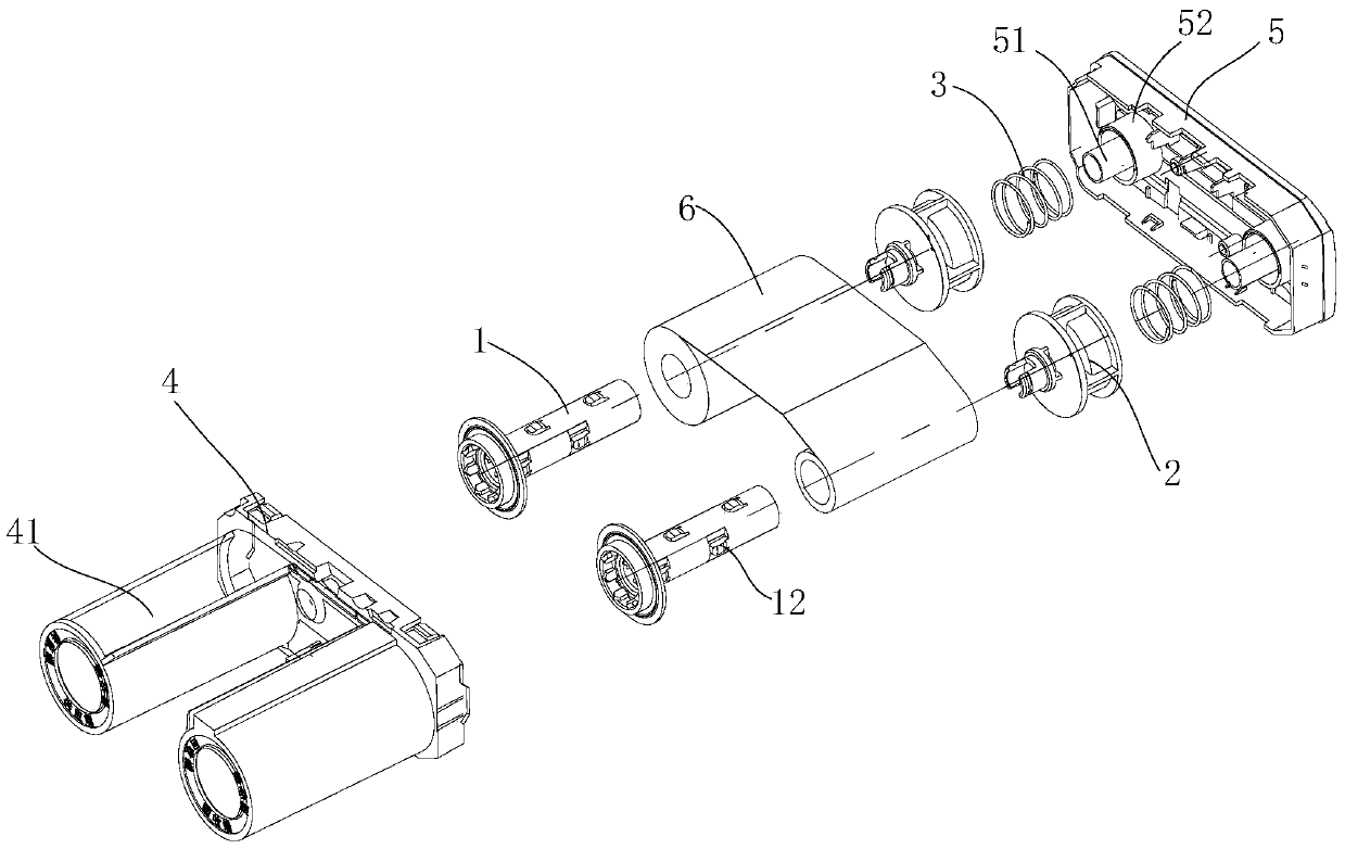
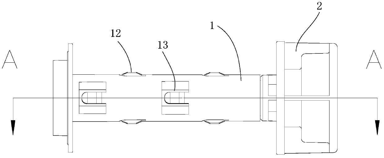
[0061] Such as Figure 1 to Figure 8 As shown, a carbon ribbon cassette includes an inner shell 4, an outer shell 5, and a ribbon shaft. The inner shell 4 and the outer shell 5 are connected by clamping. The ribbon shaft is installed in the inner shell 4. The rear end of the ribbon shaft is connected to the inner shell 4. Elastic elements 3 are arranged between the shells 5, and the carbon ribbon shaft includes a hollow support shaft 1 and a support member 2 for installing the carbon ribbon 6. The support member 2 and the rear end of the support shaft 1 are connected by a limiting structure, and the support shaft 1 The front end is the connection part that cooperates with the movement, and has flanges 16, meshing teeth 18, convex rings 17 for reducing friction, etc., and the limit structure can limit the relative movement between the support member 2 and the support shaft 1 in the axial or circumferential direction , realize the reliable connection of the support shaft 1 and t...


PUM


Abstract

The invention provides a thermal transfer ribbon box. The thermal transfer ribbon box comprises an inner shell, an outer shell and a thermal transfer ribbon shaft, wherein the inner shell and the outer shell are connected; the thermal transfer ribbon shaft comprises supporting shafts and supporting parts which are connected through limiting structures; clamping parts protruding out of the outer contour surface of each supporting shaft are arranged on each supporting shaft, and a thermal transfer ribbon is clamped on the supporting shafts through the clamping parts; the thermal transfer ribbon and the supporting shafts can synchronously rotate; and the front ends of the supporting parts are connected with the rear ends of the supporting shafts, elastic elements are arranged between the rear ends of the supporting parts and the outer shell, mounting grooves are formed in the rear ends of the supporting parts, one end of each elastic element abuts against a supporting table of the outer shell, and the other end of each elastic element is arranged in a mounting groove in an abutting manner. The supporting parts and the supporting shafts are matched with a limited concave-convex structure, matching stability of the supporting parts and the supporting shafts is ensured, coaxiality of the supporting parts and the supporting shafts in the transferring process is ensured, printing quality is improved, in-place prompt is achieved, and mounting is convenient. A plurality of clamping parts are distributed on the outer wall of each supporting shaft, mounting of the thermal transfer ribbon shaft is facilitated, and the assembly efficiency is improved.

Description

technical field [0001] The invention belongs to the technical field of printing consumables, and in particular relates to a carbon ribbon box. Background technique [0002] As a printing consumable, the ribbon cassette is widely used in the field of portable printers. The ribbon box usually includes an inner shell, an outer shell, a support shaft, and a support member. The support shaft is installed in the inner shell to support the ribbon. The front end of the support shaft is used to cooperate with the movement, and the rear end is connected to the support. On the outer shell, the inner shell and the outer shell are connected and fixed. An elastic element is arranged between the support member and the shell to push the support shaft and the support member forward in the axial direction, and produce a supporting effect through friction during the rotation process. [0003] 1. The front and rear sections of the traditional carbon ribbon shaft are matched by a gap. Due to t...

Claims


Application Information

Patent Timeline
Patent Type & Authority Patents(China)
IPC IPC(8): B41J32/00
CPCB41J32/00
Inventor 庞静
Owner CHONGQING PINSHENG TECHNOLOGY CO LTD
Why Eureka
Try Eureka