
Portable wave detector low frequency receiving voltage sensitivity performance measurer

A receiving voltage and detector technology, applied in the field of piezoelectric detector low-frequency receiving voltage sensitivity characteristic test device, can solve the problems of complicated operation, inconvenient transportation and movement, difficulty in taking it to the working site, etc. Simple operation effect

Inactive Publication Date: 2003-06-25
INST OF ACOUSTICS CHINESE ACAD OF SCI
View PDF0 Cites 6 Cited by
  • Summary
  • Abstract
  • Description
  • Claims
  • Application Information

AI Technical Summary

Problems solved by technology

[0002] In the past, the measurement of the sensitivity characteristics of the low-frequency receiving voltage of the piezoelectric detector is usually carried out by using a test system composed of a special measurement box, PC, power amplifier, A / D acquisition card, printer, standard detector, connecting cable and special operating software. , in order to produce a uniform sound field required for measurement and meet the purpose of box shock absorption during the measurement process, the volume of the measurement box reaches 80cm×80cm×80cm, and the weight reaches more than 200-300 kg. In addition, the entire measurement system consists of multiple complete machines and multiple Composed of two independent units, the operation is complicated, especially the handling and movement are inconvenient. Therefore, this measurement system is only suitable for testing and calibrating piezoelectric detectors in laboratories, factory workshops and other places.
Since piezoelectric geophones are mostly used in underground mines or in field operations such as rivers, rivers, lakes, and ponds, after a period of use, the performance parameters of piezoelectric geophones will change, and they need to be re-measured at the site of use. Calibration, and the previous test system consisting of the above-mentioned multiple complete machines and bulky measurement boxes is difficult to obtain on-site work

Method used


Image

  • Portable wave detector low frequency receiving voltage sensitivity performance measurer
  • Portable wave detector low frequency receiving voltage sensitivity performance measurer
  • Portable wave detector low frequency receiving voltage sensitivity performance measurer

Examples


Embodiment Construction

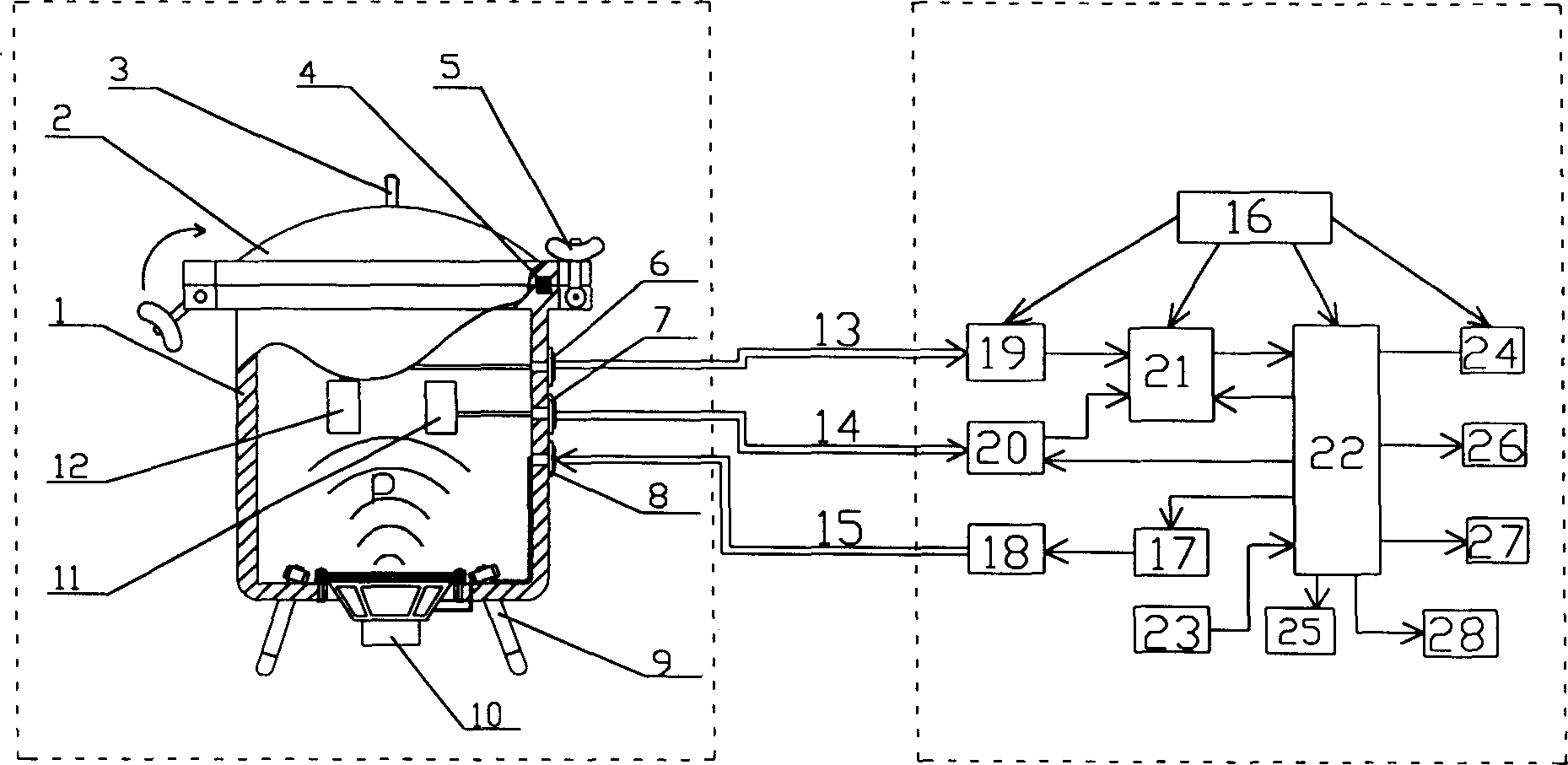
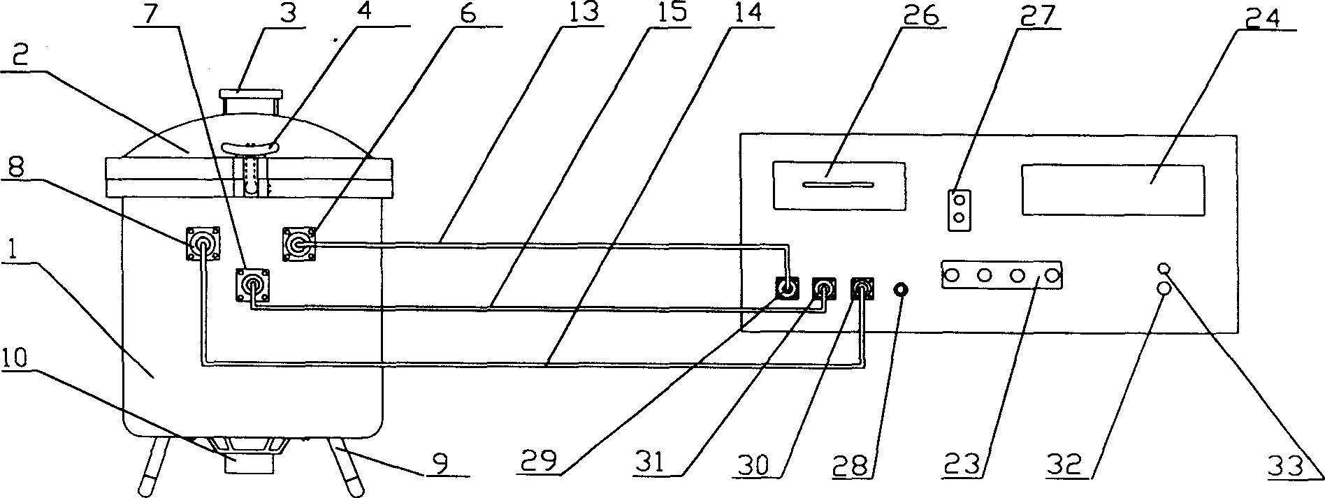
[0034] The preferred embodiment of the present invention is further described in conjunction with above-mentioned accompanying drawing now, and this embodiment is mainly made up of sound field device and circuit device two parts (as figure 1 shown), wherein the sound field device includes a tank shell 1, an upper cover 2, a handle 3, a rubber ring 4, a locking mechanism 5, signal output connection sockets 6 and 7, a drive input connection socket 8, a bracket 9, a drive sound Source 10, tested wave detector 11 and standard wave detector 12; And circuit device includes power supply 16, digitally controlled oscillator 17, power amplifier 18, fixed gain amplifier 19, programmable gain amplifier 20, A / D converter 21, single-chip microcomputer 22 , operation control key 23, display 24, memory 25, micro-printer 26, alarm device 27 and RS232 standard serial interface 28. The specific structure of this embodiment is as figure 2 As shown, the left side is the sound field device, a sou...


PUM

PropertyMeasurementUnit
Impedanceaaaaaaaaaa
Maximum poweraaaaaaaaaa

Abstract

The sensitivity performance measurer for low frequency voltage of portable wave detector includes sound field unit and electric circuit unit. The sound field unit is one sound pressure tank with driving sound source, signal output socket connected via wire to the standard detector and the measured detector inside the tank, and drive input socket connected via wire to the driving sound source, circular opening at the bottom for installing the drive sound source, which has belled mouth towards the openings. The drive input socket is also connected via cable to the output of the power amplifier in the electric circuit unit; and of the two signal output sockets one is connected via cable to the input of fixed gain amplifier in the circuit unit and the other to the input of program controlled amplifier.

Description

technical field [0001] The invention relates to a voltage sensitivity characteristic measuring instrument, in particular to a piezoelectric detector low-frequency receiving voltage sensitivity characteristic testing device. technical background [0002] In the past, the measurement of the sensitivity characteristics of the low-frequency receiving voltage of the piezoelectric detector is usually carried out by using a test system composed of a special measurement box, PC, power amplifier, A / D acquisition card, printer, standard detector, connecting cable and special operating software. , in order to produce a uniform sound field required for measurement and meet the purpose of box shock absorption during the measurement process, the volume of the measurement box reaches 80cm×80cm×80cm, and the weight reaches more than 200-300 kg. In addition, the entire measurement system consists of multiple complete machines and multiple Composed of two independent ...

Claims


Application Information

Patent Timeline
IPC IPC(8): G01D18/00G01R31/00G01V1/18
Inventor 潘潮解宝兴陈守六郝红伟金亨焕章力旺
Owner INST OF ACOUSTICS CHINESE ACAD OF SCI
Learn More