Low-profile bilayer printing ultra-wideband antenna

An ultra-broadband antenna and low-profile technology, which is applied to antennas, antenna supports/mounting devices, and devices that enable antennas to work in different bands at the same time, can solve the problems of inflexible applications, complex processing, and high profiles, and achieve good applications. Foreground, high gain effects

Active Publication Date: 2012-08-22
BEIHANG UNIV
View PDF5 Cites 10 Cited by
  • Summary
  • Abstract
  • Description
  • Claims
  • Application Information

AI Technical Summary

Problems solved by technology

Some new ultra-broadband antennas, such as vibrator antennas with reflectors, have good performance, but their profiles are generally high, and the processing is complicated, especially some antennas with non-planar reflectors, their applications are not enough flexible

Method used


Image

  • Low-profile bilayer printing ultra-wideband antenna
  • Low-profile bilayer printing ultra-wideband antenna
  • Low-profile bilayer printing ultra-wideband antenna

Examples


Embodiment Construction

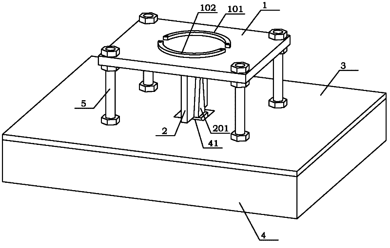
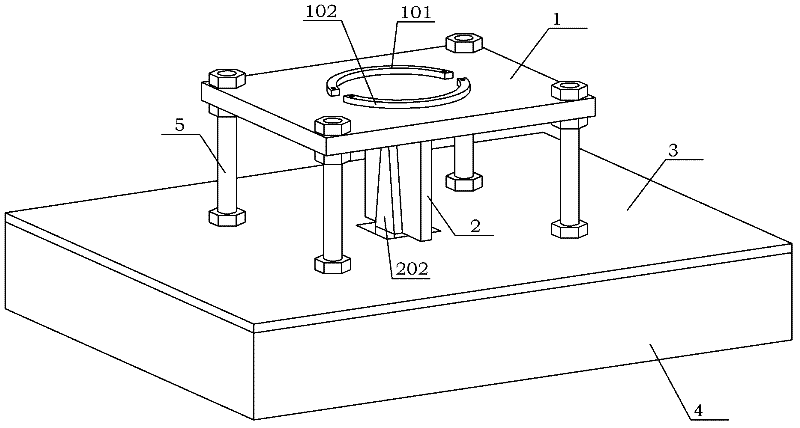
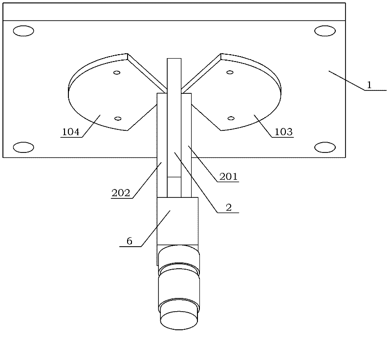
[0033] see figure 1 , Figure 1A , Figure 1B As shown, a novel low-profile double-layer printed ultra-wideband antenna of the present invention that works in the S-band and C-band, the antenna includes a transverse dielectric plate 1, a longitudinal dielectric plate 2, a reflector 3, a substrate 4 and a support column 5; Each module will be described in detail below:

[0034] (1) Horizontal dielectric board 1

[0035] see figure 1 , Figure 1A , figure 2 , Figure 2A As shown, the transverse dielectric plate 1 has a rectangular structure, the length of the transverse dielectric plate 1 is denoted as E, and the width is denoted as D, where D=4 / 5×E.

[0036]The upper plate surface 1A of the transverse dielectric plate 1 is provided with a first arc-shaped groove 1C and a second arc-shaped groove 1D, and the first arc-shaped groove 1C and the second arc-shaped groove 1D have the same structure; the first arc-shaped groove 1C Both ends are provided with A through hole 1G...


PUM


Abstract

The invention discloses a low-profile bilayer printing ultra-wideband antenna, comprising a transverse dielectric plate, a longitudinal dielectric layer, a reflecting plate, a base plate and a supporting column, wherein four supporting rods are arranged between the transverse dielectric plate and the base plate, and the longitudinal dielectric plate is arranged between the transverse dielectric plate and the base plate. Two back strips are machined on an upper plate surface of the transverse dielectric plate through a copper cladding technique, and two butterfly-shaped vibrators are machined on a lower plate surface of the transverse dielectric plate through the copper cladding technique. Baluns are machined on two plate surfaces of the longitudinal dielectric plate through the copper cladding technique. A reflection plate is machined on the base plate through the copper cladding technique. According to the low-profile bilayer printing ultra-wideband antenna disclosed by the invention, the bilayer printing antenna consisting of the antenna back strips and the vibrators is variety of a folding vibrator and is a high-grain directional novel bilayer printing vibrator antenna capable of working in an S-waveband and a C-waveband so that the miniaturization is not only realized, and wider frequency band and higher grain are provided; therefore, the antenna has very excellent characteristics of a folding vibrator, in particular the small structure size and the ultra-wide working frequency band.

Description

technical field [0001] The invention relates to a miniaturized antenna suitable for ultra-wideband systems, more specifically, a high-gain, directional, low-profile double-layer printed antenna working in S-band and C-band. Background technique [0002] In the 1980s, with the advancement of electronic science and technology, the frequency bands of radio systems such as communications and radar became wider and wider, the signal pulses became narrower and narrower, and the electromagnetic spectrum became more and more crowded. People began to pay attention to and study ultra-wideband (UWB) Electromagnetism. Around 1990, people used various time-domain numerical methods to obtain the strict transient solutions of Maxwell equations, thus laying a solid theoretical foundation for ultra-wideband electromagnetics. UWB pulse sources, UWB antennas, and UWB receiving technologies have all made breakthroughs, which have greatly promoted the research of UWB electromagnetics. UWB commu...

Claims


Application Information

Patent Timeline
Patent Type & Authority Applications(China)
IPC IPC(8): H01Q1/12H01Q1/36H01Q1/38H01Q5/01H01Q13/08H01Q19/10H01Q5/10
Inventor 吴琦王诗然苏东林
Owner BEIHANG UNIV
Why Eureka
Try Eureka