
Lubricating device of motor bearing

A technology for lubricating devices and motor bearings, applied in the directions of electromechanical devices, casings/covers/supports, electrical components, etc., can solve problems such as excessive use of grease, discharge of waste grease, narrow cavity, etc., to ensure cleanliness, thickness, etc. Thin, easy-to-process effect

Inactive Publication Date: 2012-08-22
SHANDONG HUALI ELECTRIC MOTOR GRP
View PDF4 Cites 8 Cited by
  • Summary
  • Abstract
  • Description
  • Claims
  • Application Information

AI Technical Summary

Problems solved by technology

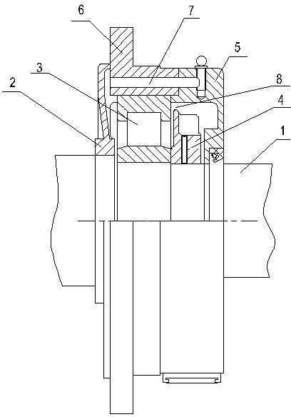
However, it is found in use that since the contact surface between the oil throwing pan 4 and the bearing 3 is a vertical surface, the width of the oil seepage space 8 is too narrow, and waste grease is difficult to be discharged by the oil seepage space 8; and if the width of the oil seepage space 8 is too large Wide, because the cavity formed between the oil throwing pan 4 and the bearing 3 is very narrow, the grease may be thrown out directly from the oil seepage gap 8, resulting in excessive use of grease

Method used


Image

  • Lubricating device of motor bearing
  • Lubricating device of motor bearing
  • Lubricating device of motor bearing

Examples


Embodiment Construction

[0019] The present invention will be further described below in conjunction with the drawings and embodiments.

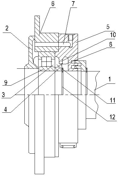
[0020] Such as figure 2 As shown, a lubricating device for a motor bearing includes a motor shaft 1, a bearing 3 installed on the bearing stand of the motor shaft 1, an oil slinger 4 installed on the motor shaft outside the bearing 3, and two sides of the bearing respectively The bearing inner cover 2 and the bearing outer cover 5 fixed by the bearing outer cover 6 are provided with an oil injection channel 7 that penetrates the cavity of the bearing inner cover 2 inside the bearing outer cover 5 and the bearing outer cover 6.

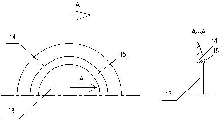
[0021] Such as image 3 As shown, the oil slinger 4 in the lubricating device is a disc with an inner hole 13, combined image 3 It can be seen from the AA cross-sectional view in the middle that the thickness of the slinger body 15 is divided into two parts. The surface of the disc is bounded by the contact contour circle 14 with the bearing inn...


PUM


Abstract

The invention relates to a motor matching device. In order to solve the technical problems that oil throwers of lubricating devices of existing motor bearings cannot prevent lubricating grease from being thrown off and waste oil grease can not discharged, lubricating devices of conventional motor bearings are improved and the innovations are that the oil thrower is a round tray with an inner hole, the thickness of the oil thrower is tapered in a radial direction outwards from a contacting contour circle of an inner sleeve of a bearing to the oil thrower, the oil thrower and a non contacting face of the bearing are in a same plane, the oil thrower and the bearing are assembled in a combining mode, a V-shaped hollow cavity is formed between the oil thrower and the bearing, the height of the oil thrower is lower than the diameter of the inner sleeve of the bearing, an annular boss is assembled on the inner wall of an outer cover of the bearing, a spigot is arranged on the inner wall of the outer cover of the bearing, and a narrow gap serving as an oil overflowing channel is formed between the outer edges of the boss and the oil thrower. The lubricating device is easy to process, convenient to install, and guarantees not only residual amount of the lubricating grease in a bearing chamber but also cleanness of the lubricating grease and discharge of the waste oil grease.

Description

[0001] Technical field [0002] The invention relates to a matching device for a motor, in particular to a lubricating device for a motor bearing. Background technique [0003] During the operation of the motor, the bearing bears the effect of axial force and radial force. The rolling element rubs against the inner and outer shell of the bearing during rotation to generate heat and wear. A certain amount of grease must be stored in the bearing chamber to lubricate the bearing And heat dissipation, the stock of grease generally does not exceed one-third of the total amount of the bearing chamber. Small motors mostly use closed bearings, and large and medium-sized motors are open bearings. It is necessary to ensure the cleanliness of grease, replenish new grease in time, and discharge waste grease after use to ensure good bearing operation. [0004] At present, common lubrication devices for motor bearings are such as figure 1 As shown, it includes a bearing 3 installed on the beari...

Claims


Application Information

Patent Timeline
Patent Type & Authority Applications(China)
IPC IPC(8): H02K5/16
Inventor 孙晓霞张红红李海成
Owner SHANDONG HUALI ELECTRIC MOTOR GRP
Learn More