Ball bearing cage

A cage and ball bearing technology, applied to bearings, bearing components, shafts and bearings, etc., can solve problems such as abnormal bearing noise, ball bearing damage, cage instability, etc., to save costs and reduce transportation damage.

Inactive Publication Date: 2012-08-22
SCHAEFFLER TECH AG & CO KG
View PDF6 Cites 2 Cited by
  • Summary
  • Abstract
  • Description
  • Claims
  • Application Information

AI Technical Summary

Problems solved by technology

This effect can lead, among other consequences, to overheating of the ball bearing, breakdown of the lubricant or even damage to the ball bearing
Such cage instability is in most cases also accompanied by increased, abnormal bearing noise

Method used


Image

  • Ball bearing cage
  • Ball bearing cage
  • Ball bearing cage

Examples


Embodiment Construction

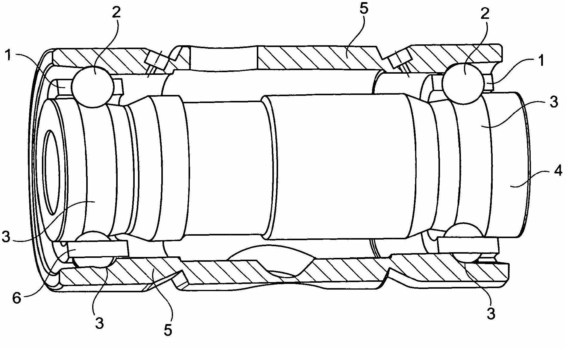
[0029] Depend on figure 1 A cross-section of a rolling bearing arrangement of a shaft bearing in a turbocharger is obtained. The turbocharger has a turbine rotor (not shown) which drives a charging wheel (not shown) of the turbocharger via a rotatably mounted shaft 3 . The fast-rotating shaft 3 is supported via two angular contact ball bearings 1 arranged in an O-shape, which support the shaft 3 relative to a stationary housing or bearing seat 5 .

[0030] Both the inner raceway 3 and the outer raceway 3 of the two angular contact ball bearings 1 are inserted directly into the shaft 3 or into the bearing housing 5 . Rolling bodies 2 (in this case balls 2 ) are arranged in two ball rows between the respective inner raceway 3 and the associated outer raceway 3 of the two angular contact ball bearings 1 .

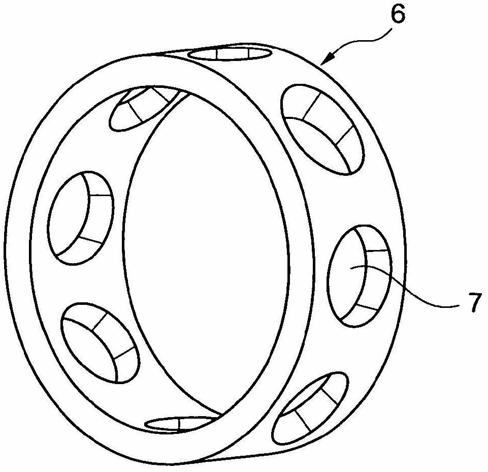
[0031] To hold the balls 2 at a distance, the ball rows of the two angular contact ball bearings 1 are correspondingly arranged in a solid cage 6 (hereinafter referred to as...


PUM


Abstract

The invention relates to a ball bearing cage having an annular rolling element retaining body, comprising ball sockets distributed around a circumference of the rolling element retaining body for receiving spherical rolling elements. According to the invention, the ball sockets are distributed around the circumference, such that distances between two adjacent ball sockets increase in a circumferential direction, starting at a smallest distance between two adjacent sockets at least in a circumferential sector.

Description

technical field [0001] The invention is in the field of high-efficiency rolling bearings, in particular for supporting shafts that rotate at high speeds, such as in turbochargers, but also in drives or in high-speed rotating turbines (such as gas turbines) on the shaft supported there. Background technique [0002] Such a turbocharger with high-efficiency roller bearings (angular contact ball bearings) is known from DE 112004002481T5. The turbocharger has a turbine rotor which drives a charging wheel of the turbocharger via a rotatably mounted shaft. The high-speed rotating shaft is supported according to DE 112004002481T5 via two angular contact ball bearings, which support the shaft relative to the stationary housing. [0003] Ball bearings, such as angular contact ball bearings or deep groove ball bearings, are known and generally have an inner ring, an outer ring and rolling bodies or balls arranged in the circumferential direction between the inner ring and the outer ...

Claims


Application Information

Patent Timeline
Patent Type & Authority Applications(China)
IPC IPC(8): F16C33/38
CPCF16C33/3843F16C19/184F16C2240/30F16C2360/24
Inventor 阿伦·克里斯
Owner SCHAEFFLER TECH AG & CO KG
Why Eureka
Try Eureka