
Kettlebell and method of manufacturing the same

A technology for kettlebells and counterweights, applied in the direction of dumbbells, heavy objects, etc., can solve the problems of easy slipping, difficult processing, slipping handles or handles, etc., and achieve the effect of increasing the contact area, good sweat absorption effect, and firm fixation

Inactive Publication Date: 2015-11-25
南通力神健身用品有限公司
View PDF6 Cites 0 Cited by
  • Summary
  • Abstract
  • Description
  • Claims
  • Application Information

AI Technical Summary

Problems solved by technology

One is inconvenience
Especially in winter, the handle or handle tends to be cold, making it very unsuitable for exercise when holding
The second is that the sweat absorption effect is poor. People tend to sweat when exercising. When the sweat flows to the hands or handles, the handles or handles will slip
Especially for injection molded (or blow molded) kettlebells, whose smooth plastic handles tend to slip
Slippery handles or handles can cause the dumbbell or kettlebell to fall out of the exerciser's hand if the handle or handle needs to be held hard and the handle or handle is subject to high forces
Especially with injection molded (or blow molded) kettlebells, which may have to be constantly turned over during use, the slippery plastic handles are more likely to fall out of the exerciser's hands
The third is that the color is single, and it is impossible to set rich colors
Existing injection molding (or blow molding) dumbbells or kettlebells, if you need to set a variety of color patterns, processing is very difficult
Especially when only local areas such as handles or handles need to be colored, processing is more difficult

Method used


Image

  • Kettlebell and method of manufacturing the same
  • Kettlebell and method of manufacturing the same
  • Kettlebell and method of manufacturing the same

Examples


Embodiment 1

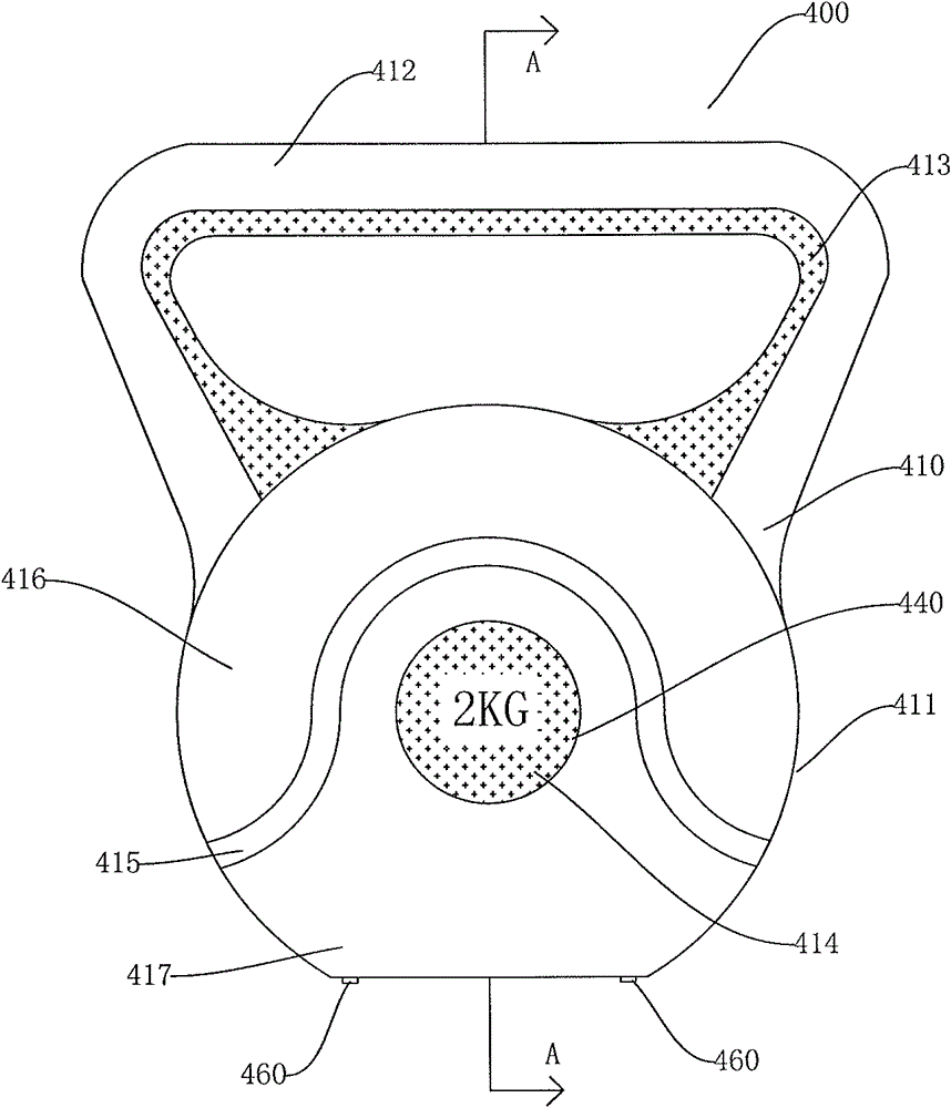
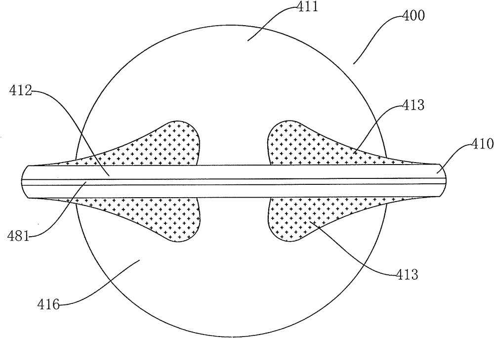
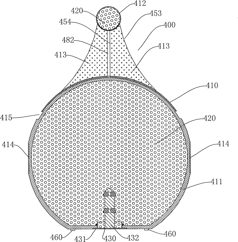
[0134] figure 1 Shown is a front view of a kettle dumbbell. figure 2 for figure 1 Top view of a kettle-style dumbbell. image 3 for figure 1 A-A section view. The dumbbell in this embodiment is symmetrical about the axis of the A-A section line. Such as figure 1 , figure 2 with image 3 As shown, the dumbbell 400 has a kettle shape. The front view and the rear view are symmetrical. The dumbbell 400 structure includes a shell 410 and a counterweight 420 filled in the shell. The housing 410 includes a dumbbell body housing 411 and a handle housing 412. The handle shell 412 is disposed above the dumbbell body shell 411, and its gripping part is cylindrical, and both ends are connected to the dumbbell body shell 411. The dumbbell body shell 411 and the handle shell 412 are integrally formed. The handle housing 412 is used for holding. The housing 410 is blow molded. During the blow molding process of the housing 410, an outer clamping line 481 and an inner clamping line 482...

Embodiment 2

[0143] Picture 11 This is the front view of the dumbbell in Example 2. Such as Picture 11 As shown, the dumbbell is composed of a shell and a weight filled in the shell. The dumbbell shell includes a handle shell 601 and two dumbbell head shells (602, 603). Two dumbbell head shells (602, 603) are respectively arranged at two ends of the handle shell 601. The handle housing 1 and the dumbbell head housings (602, 603) are an integral structure. The handle housing 601 is cylindrical. The grip portion of the handle housing 601 is provided with six piles 611 (three pieces are shown in the figure) evenly spaced along the circumferential direction. The thickness of the fleece 611 is 0.5 mm. The fleece 611 is arranged on the insert. The insert is arranged on the handle housing 601. An opening is provided at the end of the dumbbell head 603, and the counterweight is filled into the cavity of the housing through the opening. After filling, use the lid 430 to seal the opening.

[...

Embodiment 3

[0148] Figure 14 Shown is a schematic diagram of the lid structure in Example 3. Figure 15 It is a cross-sectional view of the cover A-A in Example 3. Such as Figure 14 , 15 As shown, the cover 430 includes a circular bottom plate 431. The thickness of the bottom plate 431 is the same as the height of the step 419. A cylinder wall 434 is provided on the bottom plate 431. The cylinder wall 434 is arranged in a circle around the pillar 432. The bottom plate 431 and the cylinder wall 434 form a cylinder. The cross-sectional area enclosed by the cylinder wall 434 is smaller than the cross-sectional area of ​​the bottom plate 431. The upper end of the cylinder wall 434 has an inclined surface 4341. The outer peripheral surface of the cylinder wall 434 is provided with a flange 435 protruding from the cylinder wall 434. The side wall 4351 of the flange 435 is arc-shaped. The flange 435 is separated from the bottom plate 431 by a set distance, and a slot 436 is formed between...


PUM


Abstract

The invention discloses a dumbbell, which comprises a case and a balance weight object filled in the case, wherein the case is provided with an opening. The dumbbell is characterized by also comprising a cover, the cover is arranged at the opening part for sealing the opening, the cover comprises a bottom plate, and a tube wall is arranged on the bottom plate. The cover of the dumbbell disclosed by the invention is provided with the tube wall, the balance weight object in the dumbbell can be combined with the tube wall into a whole after being concreted, and the cover can be prevented from falling. The upper end size of a projecting element arranged on the upright post is smaller than the lower end size, the upright post can be conveniently inserted into the balance weight object, the pulling-out resistance of the upright post can also be increased, and the fixation is firmer. The tube wall is arranged on a bottom cover, the contact area of the bottom cover and the balance weight object is increased, and the fixation is firmer. A clamp groove is arranged on the tube wall, and the stability of the cover on the case is further enhanced. The designed clamp groove can prevent the cover form falling before the balance weight object is concreted. The side wall of a flange adopts the arc-shaped design, and the flange can be conveniently inserted into the case. The area of the cross section surrounded by the tube wall is smaller than the area of the cross section of the bottom plate, so the cover can be inserted into the case for increasing the bonding area of the cover and the balance weight object, and the bottom plate can also be clamped outside the case for completely sealing the opening.

Description

Technical field [0001] The invention relates to a method for manufacturing dumbbells and kettlebells, a blow-molded kettlebell bottom cover and a blow-molded kettlebell containing the same. Background technique [0002] A dumbbell structure includes a shell, and the shell is filled with counterweights. The shell is provided with an opening, and the counterweight is filled into the shell through the opening, and then the opening is sealed with a cover. However, the commonly used cover is glued to the shell, and its installation is not firm and easy to fall off, causing damage to the dumbbell. Especially for kettlebells, the lid is set at the bottom, which makes it easier to fall off. [0003] Dumbbells or kettlebells with a shell structure have a structure for holding, which is called a handle or a handle. Commonly used handles or handles have many shortcomings and deficiencies. One is inconvenience. Especially in winter, the temperature of the handle or handle is often low, an...

Claims


Application Information

Patent Timeline
Patent Type & Authority Patents(China)
IPC IPC(8): A63B21/072
Inventor 龚协平
Owner 南通力神健身用品有限公司
Learn More