Projection system and light-emitting device thereof

A technology of a light-emitting device and a light-splitting device, applied in the optical field, can solve the problems of low efficiency, high cost, brightness loss, etc., and achieve the effects of reducing cost, improving efficiency, and avoiding energy loss

Active Publication Date: 2012-08-29
APPOTRONICS CORP LTD
View PDF15 Cites 54 Cited by
  • Summary
  • Abstract
  • Description
  • Claims
  • Application Information

AI Technical Summary

Problems solved by technology

[0009] However, after the above filter modification, the brightness of the green light is lost by 12%, and the brightness of the red light is lost by 45%
Therefore, the three-chip projection system of the prior art generally has the technical problems of high cost and low efficiency.
[0010] To sum up, it is necessary to provide a projection system to solve the common technical problems of high cost and low efficiency in the prior art three-chip projection system

Method used


Image

  • Projection system and light-emitting device thereof
  • Projection system and light-emitting device thereof
  • Projection system and light-emitting device thereof

Examples


Embodiment Construction

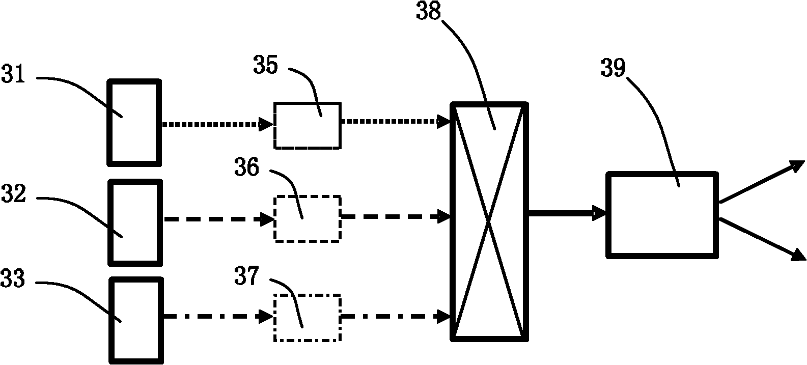
[0065] See Image 6 , Image 6 It is a structural schematic diagram of a preferred embodiment of the projection device of the present invention. like Image 6 As shown, the projection device in this embodiment mainly includes a wide-spectrum light source 61 , a spectroscopic device 62 , light modulation devices 63 , 64 and 65 , a light combining device 66 and a projection device 67 .

[0066] The broadband light source 61 produces a broadband light. The spectroscopic device 62 splits the wide-spectrum light generated by the wide-spectrum light source 61, and outputs at least two monochromatic lights of different colors traveling along different paths. In this embodiment, the monochromatic light may be primary color light, of course, in other embodiments, it may also be monochromatic light of other wavelengths, or even light with a certain spectral range.

[0067] In this embodiment, the wide-spectrum light is white light, and the light splitting device 62 splits the white ...


PUM


Abstract

The embodiment of the invention provides a projection system and a light-emitting device of the projection system. The light-emitting device comprises an exciting light source, a wavelength conversion device, a driving device and a beam splitting device. The exciting light source is used to generate exciting light; the wavelength conversion device comprises a wavelength conversion layer which converts at least part of the exciting light to excited light; and the excited light is wide-spectrum light or the light mixture of the excited light and the exciting light which is not converted by the wavelength conversion layer forms wide-spectrum light. The driving device is used to drive the exciting light to move in a manner relative to the wavelength conversion layer. The beam splitting device is used to split the wide-spectrum light into at least two types of monochromatic light which is transmitted along different paths. Through the manner, the costs of the projection system and the light-emitting device of the projection system provided by the embodiment of the invention can be reduced and the efficiency can be improved.

Description

technical field [0001] The invention relates to the field of optical technology, in particular to a projection system and a light emitting device thereof. Background technique [0002] Currently, ultra-high pressure mercury lamps (UHP lamps) are generally used as light sources in existing projectors. Among them, the UHP lamp utilizes the discharge of ultra-high pressure mercury vapor (above 1Mpa) to obtain visible light. However, since mercury is easy to cause environmental pollution, the industry is seeking an environmentally friendly light source to replace UHP lamps. [0003] See figure 1 , figure 1 It is a structural schematic diagram of a light source system for a projector in the prior art. like figure 1 As shown, the light source system includes a solid-state light source 11 , a focusing system 12 , a fluorescent device 13 and a driving device 14 . The solid-state light source 11 generates excitation light, which is focused by the focusing system 12 and then inc...

Claims


Application Information

Patent Timeline
Patent Type & Authority Applications(China)
IPC IPC(8): G03B21/20G02B27/10F21V14/02F21V7/22F21V9/10F21V9/40
CPCG02B27/1006G03B21/204G03B21/208G03B33/12
Inventor 胡飞李屹杨毅
Owner APPOTRONICS CORP LTD
Why Eureka
Try Eureka