
Three-wheel road sweeper

A road sweeper and three-wheel technology, applied in the field of road sweepers, can solve the problems of lack of special vehicles, large space for special vehicles, self-weight of batteries, etc., and achieve the effects of prolonged service life, low configuration capacity, and easy operation.

Inactive Publication Date: 2012-09-05
赵国贵
View PDF2 Cites 9 Cited by
  • Summary
  • Abstract
  • Description
  • Claims
  • Application Information

AI Technical Summary

Problems solved by technology

Pure electric vehicle technology is not suitable for road sweepers. Road sweepers need not only variable power to drive the vehicle to drive at variable speeds, but also stable power to drive the on-board operating devices to work stably; generally, they must be able to operate in double shifts. Due to weather or road pollution, it is even necessary to be able to meet temporary arrangements for overtime work; the battery of a pure electric road sweeper is high in manufacturing cost, heavy in weight, and occupies a large space in a special vehicle. The battery is too heavy to consume energy when driving. The relatively long charging time cannot meet the uncertain continuous operation time requirements, and it is impossible to install air conditioners to ensure operating comfort and avoid drivers from being polluted by vehicle exhaust and cleaning dust on the road, lacking the motivation to guarantee humanized design

Method used


Image

  • Three-wheel road sweeper
  • Three-wheel road sweeper
  • Three-wheel road sweeper

Examples


no. 1 example

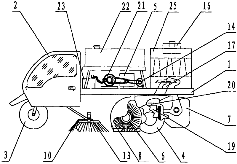
[0031] figure 1 It is a structural schematic diagram of the first embodiment of a road sweeper according to the present invention.

[0032] like figure 1 As shown, the present embodiment is a kind of three-wheeled road sweeper, and just three wheels are arranged, and a steering wheel 3 is installed at the front end of the vehicle frame 1, two rear wheels 4 are installed at the rear of the vehicle frame 1, and a driving wheel 4 is installed at the front of the vehicle frame 1. Room 2; a circular side brush 13 is installed on both sides of the front end or the middle of the vehicle frame 1. The sweeping brush 13 is put down during operation and lifted during transition, and is installed behind the side brush 13 and in the middle of the vehicle frame 1. There is a rolling brush 6; a dustbin 7 is installed under the vehicle frame 1 behind the rolling brush 6, and the guide plate 8 semi-closed under the vehicle frame 1 covers the rolling brush 6 and the dustbin 7; Clean water tan...

no. 2 example

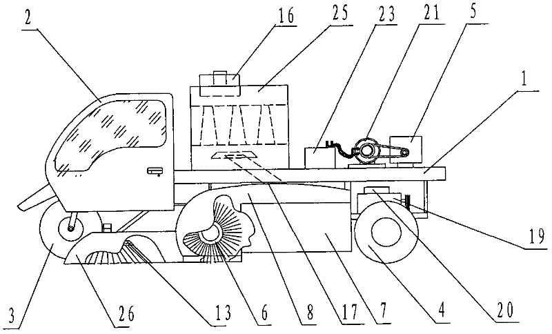
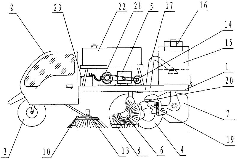
[0038] This embodiment proposes several more air-exhausting and dust-removing structures of a hybrid road sweeper, figure 2 It is a schematic diagram of the structure of dry cleaning and dry dust control in the second embodiment, image 3 It is a schematic structural diagram of the water bath dust collector of the second embodiment.

[0039] 1. Dry cleaning and dry dust removal structure. See figure 2 A semi-enclosed dust collection tent 26 with a cover sweep brush 13 installed on the vehicle frame 1, the semi-enclosed dust collection tent 26 communicates with the semi-closed guide plate 8, and is closed or disassembled on the side brush 13 and / or the vehicle frame 1 Installed water spray nozzle 10, or do not install water spray nozzle 10 on the side brush 13 and / or vehicle frame 1, the bag filter 25 that is installed on the vehicle frame 1 is sealed and fan 16 is installed and exhausted, and road sweeper sweeps The dust raised during dry cleaning by the brush 13 is sucke...

no. 3 example

[0045] Figure 4 It is a schematic diagram of the structure of the third embodiment of a road sweeping vehicle according to the present invention.

[0046] Such as Figure 4 As shown, a three-wheeled road sweeper is provided with three wheels, a steering wheel 3 is installed at the front of the frame 1, two rear wheels 4 are installed at the rear, and a cab 2 is installed at the front of the frame 1, and the cab 2 is sealed. And air-conditioning is installed; two circular side brushes 13 are installed on both sides of vehicle frame 1 front end or middle part, and dustbin 7, clear water tank 22, water pump 14, suction cylinder 30, blower fan 16 are installed on vehicle frame 1 The air inlet is connected to the dustbin 7, and the air outlet of the fan 16 is under the dustbin 7 towards the rear of the road sweeper. There is a suction cup 31 installed behind the side brush 13 and in the middle of the frame 1. The suction cylinder 30 is installed on the suction cup 31. 30 Unicom ...


PUM


Abstract

The invention provides a three-wheel road sweeper driven by mechanical and electric hybrid power. The road sweeper is provided with two power sources, namely an engine and a storage battery; under the condition that a vehicle-mounted working device is driven to work stably, the engine also drives a generator and is connected with a motor A through a motor controller to drive the road sweeper to run at variable speed; the generator is simultaneously connected with the storage battery; the storage battery is also connected with the motor A through the motor controller; the part of the instantaneous power generation quantity of the generator, which is greater than the demand of the motor A, charges the storage battery; the part of the instantaneous power generation quantity of the generator, which is smaller than the demand of the motor A, is supplied by the storage battery; and the storage battery alternates charge and discharge. The road sweeper is small, flexible in turning, strong in working capability and good in dust control effect; compared with a four-wheel road sweeper, the invention has the advantages that the three-wheel road sweeper is suitable for sweeping bicycle lanes and sidewalks and is particularly suitable for sweeping urban laneways; compared with a micro road sweeper, the invention has the advantages that the three-wheel road sweeper is strong in working capability, and an operator is not subjected to pollution of automobile exhaust and dust due to an air conditioner; and compared with a pure electric road sweeper, the invention has the advantages that the three-wheel road sweeper can unlimitedly and continuously work.

Description

technical field [0001] The invention relates to a road sweeper, in particular to a three-wheeled road sweeper. Background technique [0002] The city has popularized the use of road sweepers to clean the roads, but there are deficiencies in the prior art. At present, medium-sized or large-scale road sweepers are commonly used. Such road sweepers are expensive, have high engine power, high fuel consumption, and high operating costs. Especially, four-wheel road sweepers with such a width cannot clean bicycle lanes and sidewalks. It is impossible to enter the urban roadway for cleaning, and many motor vehicle lanes only need to be cleaned on the side of the road, and do not need a large cleaning width. There are also small road sweepers, all of which are four-wheeled and powered by engines. There are also miniature three-wheel sweepers that are only suitable for indoor or courtyard use. When used outdoors, the operating efficiency is low. Basically, the battery is used as the...

Claims


Application Information

Patent Timeline
Patent Type & Authority Applications(China)
IPC IPC(8): E01H1/08E01H1/10
Inventor 赵国贵
Owner 赵国贵
Learn More