Hybrid dust absorption environmental sanitation vehicle and hybrid sweeping environmental sanitation vehicle

A hybrid, sanitation vehicle technology, applied in road cleaning, construction, cleaning methods, etc., can solve the problems of low hydraulic transmission transmission efficiency, no dust, whether the fan exhaust air needs to spray dust, and the dust is difficult to remove.

Inactive Publication Date: 2009-03-25
赵国贵
View PDF2 Cites 29 Cited by
  • Summary
  • Abstract
  • Description
  • Claims
  • Application Information

AI Technical Summary

Problems solved by technology

The shortcomings of the above patents are that the road sweeper with dual engine configuration has high fuel consumption and high emissions
The shortcomings of the above patents are low transmission efficiency and high fuel consumption of hydraulic transmission
In this technical solution, the centrifugal force generated by the high-speed rotation of the fan impeller cannot separate the fine dust from the air flow well. The fine dust that cannot be separated is continuously accumulated and may generate dust when it enters the dust suction plate through the air duct and is blown out from the air nozzle. The closed loop of all the airflow makes the air nozzle blow back in the vacuum tray, which affects the effect of the vacuum truck on the heavy garbage on the ground. The dust and garbage stuck on the ground are difficult to remove without a brush.
[0008] At present, it is still difficult to find information on the application of hybrid ele

Method used


Image

  • Hybrid dust absorption environmental sanitation vehicle and hybrid sweeping environmental sanitation vehicle
  • Hybrid dust absorption environmental sanitation vehicle and hybrid sweeping environmental sanitation vehicle
  • Hybrid dust absorption environmental sanitation vehicle and hybrid sweeping environmental sanitation vehicle

Examples


no. 1 example

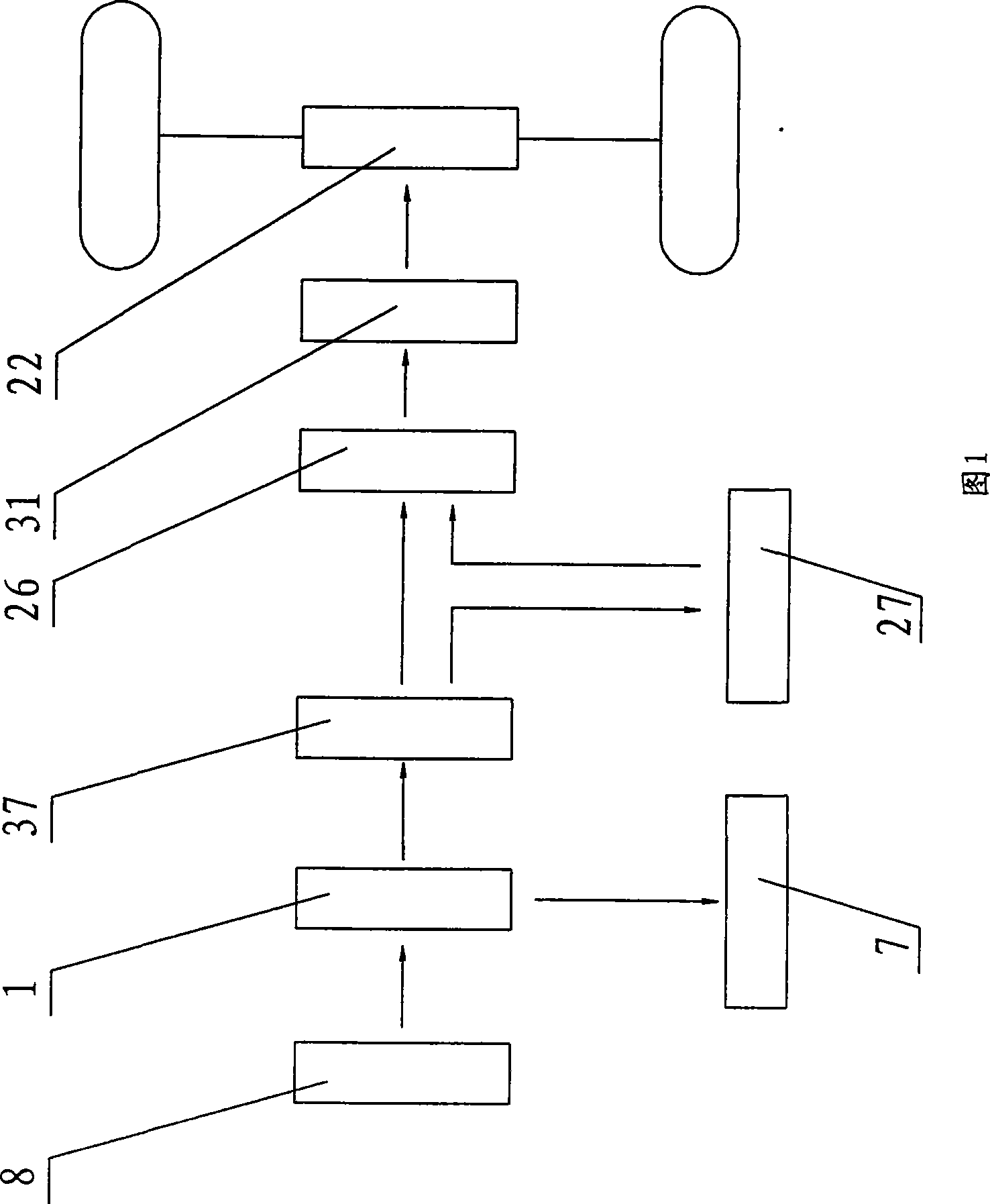
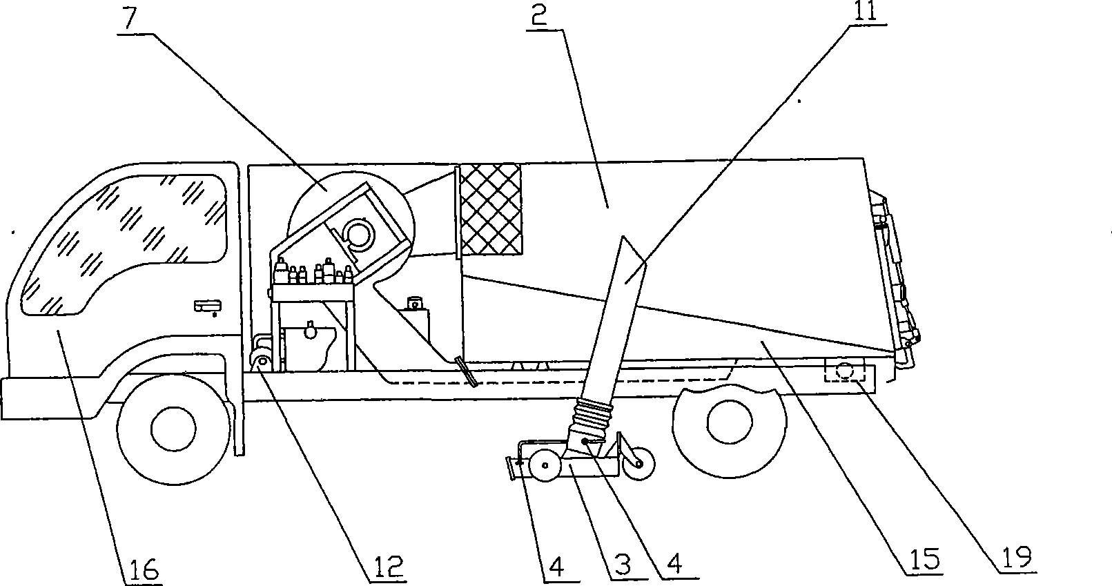
[0047] The first embodiment, a hybrid dust-collecting sanitation vehicle, as shown in Figure 1 and image 3 Shown. Figure 1 is a block diagram of the basic transmission structure of the hybrid dust-collecting sanitation vehicle of the present invention. image 3 It is a schematic diagram of the structure of a hybrid dust-collecting sanitation vehicle according to the first embodiment of the present invention.

[0048] The frame 19 is equipped with a cab 16, an engine 8, a dustbin 2, a fan 7, a suction cup 3, a suction tube 11, and a rear axle shaft 22. A suction tube 11 is installed on the suction cup 3 to communicate with the dustbin 2. The air inlet of the fan 7 is connected to the dustbin 2; the engine 8 is connected to the transmission gear transfer case 1, and the gear transfer case 1 is respectively connected to the transmission silicon rectifier generator 37 and the fan 7, and the silicon rectifier generator 37 is also connected to the battery 27 and a power converter 26, t...

no. 3 example

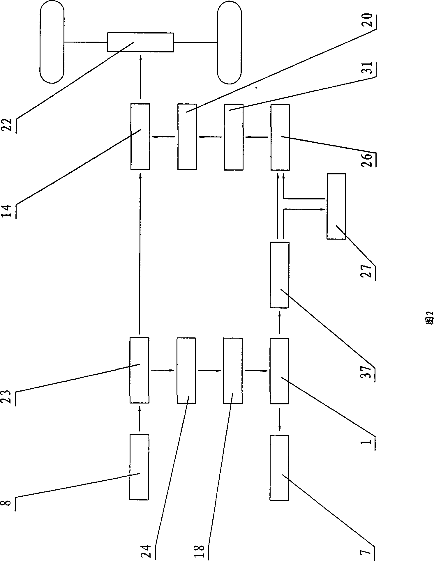
[0067] The third embodiment, the third embodiment is a sweep-suction cleaning and dust-collecting sanitation vehicle with a hybrid power transmission structure, which is an extension of the chassis transmission structure and dust-collecting operation structure of the second embodiment, such as Figure 5 , Figure 6 Shown. Figure 5 It is a schematic diagram of the structure of the cleaning and dust collection sanitation vehicle according to the third embodiment of the present invention. Figure 6 for Figure 5 Schematic of the top view.

[0068] On the basis of the chassis transmission structure of the second embodiment, butterfly sweeping brushes 6 are respectively installed on both sides of the frame 19; the gear transfer case 1 is sequentially connected to drive hydraulic pumps and hydraulic motors to drive butterfly sweeping brushes 6 for cleaning Or the battery 27 is connected to the DC motor to drive the butterfly sweeping brush 6 for cleaning; the suction cup 3 is installed...

no. 7 example

[0087] The seventh embodiment, a hybrid power sweeping sanitation vehicle, such as Picture 12 Shown. Picture 12 It is a schematic top view of the structure of a hybrid pure sweeping sanitation vehicle according to the seventh embodiment of the present invention.

[0088] The invention provides a hybrid sweeping sanitation vehicle, which includes a frame 19 on which an engine 8, a butterfly sweeping brush 6, a rolling brush 35, a dustbin 2, a water tank 15, a water pump 12, and a rear axle are installed The shaft 22 is mounted with a cab 16 on the frame 19, the butterfly brushes 6 are mounted on both sides of the head of the sanitation vehicle and / or on both sides of the middle of the frame 19, and the roller brushes 35 are mounted on The butterfly sweep brush 6 is placed horizontally under the frame 19 and in the middle of the sanitation vehicle. The upper surface of the rolling brush 35 communicates with the entrance of the trash bin 2, and the engine 8 is connected to the tran...


PUM


Abstract

The invention relates to a hybrid vacuum sweeper. A chassis is provided with an engine, a gear transfer case, a silicon rectifying generator, a storage battery, a power converter, a motor, a dustbin, a suction tube, a suction cup, a fan, a water tank and a water pump. The engine drives the silicon rectifying generator and the fan respectively. The silicon rectifying generator is connected with the power converter and the storage battery to output generated electric current. The power converter is connected with the motor to drive a rear axle shaft to drive the vacuum sweeper to run. The fan sucks dust and garbage on the ground in front of the suction cup into the dustbin through the dustbin, the suction tube and the suction cup. The water pump pumps water from the water tank to control the dust in the suction tube and the suction cup by a wet method. In the invention, a hybrid drive technology is applied to a special urban environment sanitary vehicle with vehicle-mounted operating devices, and the special vehicle has an oil-saving effect due to the use of a single engine as well as good operation effects; and a hybrid drive mechanism continuously generates electricity and overcomes the drawback that an electrical vehicle can not work for a long time due to the limitation from the capacity of the storage battery.

Description

Technical field [0001] The invention relates to a hybrid power sanitation equipment, in particular to a hybrid power dust suction sanitation vehicle and a hybrid power sweeping sanitation vehicle. Background technique [0002] At present, mechanized equipment is increasingly used to clean urban roads, and vacuum cleaners and sweepers have been widely promoted. In sanitation vehicles with on-board operating devices, such as sweepers, high-pressure washing vehicles and other special sanitation vehicles, two engines are generally installed on large and medium-sized vehicles. The main engine is responsible for driving the vehicle, and the auxiliary engine is responsible for providing stable power. Drive the vehicle-mounted operating device to work. On small sanitation vehicles, due to the space constraints of the vehicle, a single engine is generally used to drive multiple hydraulic pumps connected in series, and several hydraulic pumps respectively drive hydraulic motors to drive th...

Claims


Application Information

Patent Timeline
IPC IPC(8): E01H1/08E01H1/04
Inventor 赵国贵赵宏坚
Owner 赵国贵
Why Eureka
Try Eureka