Composite transmission environmental sanitation dumper

A compound transmission and cleaning vehicle technology, applied in the field of compound transmission sanitation cleaning vehicles, can solve the problems of high fuel consumption, high manufacturing cost of power batteries, low hydraulic transmission transmission efficiency, etc.

Inactive Publication Date: 2009-03-25
赵国贵
View PDF2 Cites 12 Cited by
  • Summary
  • Abstract
  • Description
  • Claims
  • Application Information

AI Technical Summary

Problems solved by technology

The shortcomings of the above patents are that the road sweeper with dual engine configuration has high fuel consumption and high emissions
The shortcomings of the above patents are low transmission efficiency and high fuel consumption of hydraulic transmission
Pure electric vehicles must meet the pow...

Method used


Image

  • Composite transmission environmental sanitation dumper
  • Composite transmission environmental sanitation dumper
  • Composite transmission environmental sanitation dumper

Examples


no. 1 example

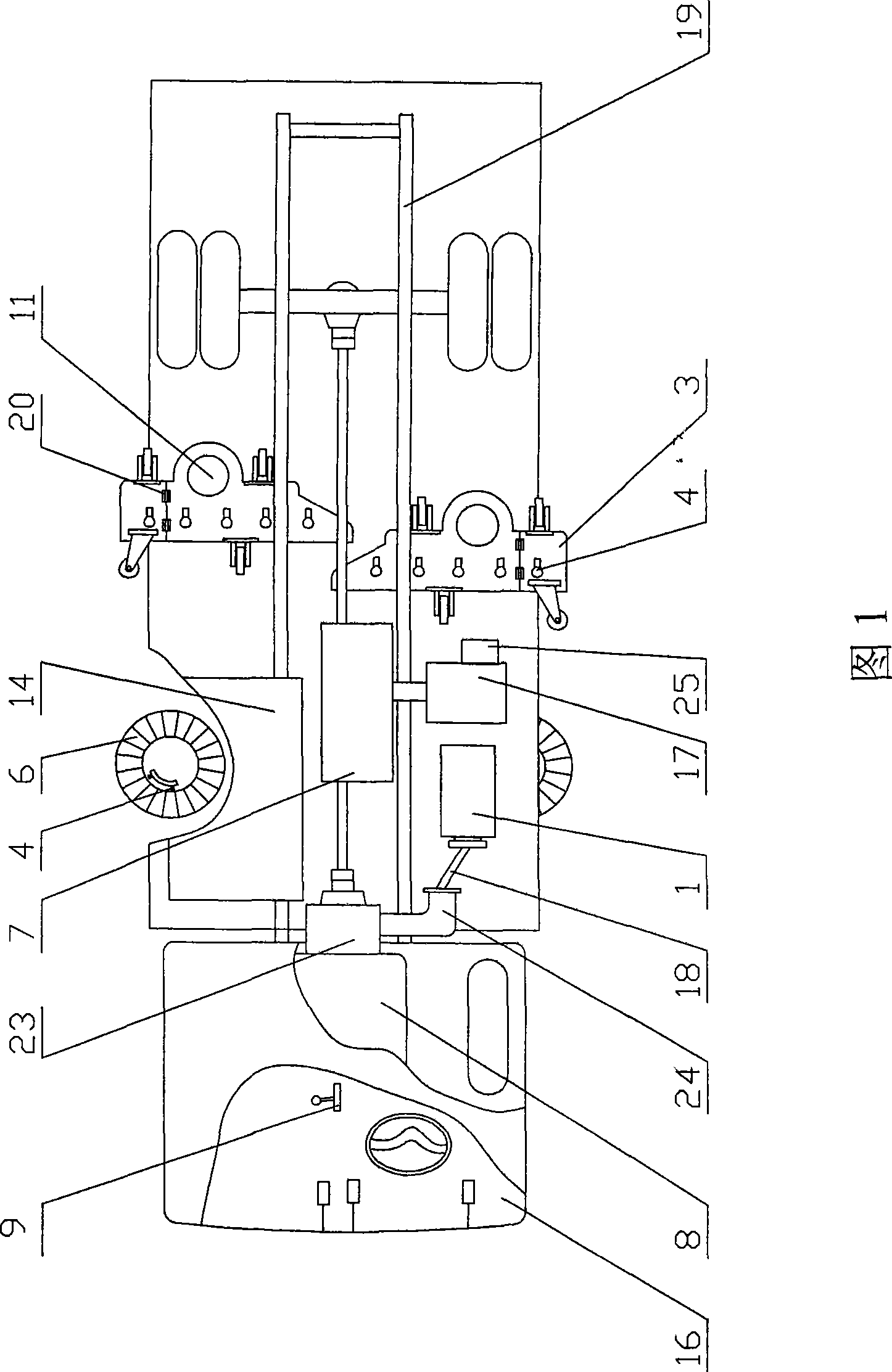
[0036] The first embodiment is a composite transmission dust suction sanitation cleaning vehicle, as shown in FIG. 1 . Fig. 1 is a schematic diagram of the basic structure of the dust-absorbing and sanitation cleaning vehicle of the present invention.

[0037] Said vehicle frame 19 is equipped with driver's cab 16, engine 8, dustbin 2, blower fan 7, sucker 3, suction cylinder 11, and said suction cup 3 is equipped with suction cylinder 11 Unicom dustbin 2, and the intake of said blower fan 7 The tuyere is connected to the dustbin 2, and the engine 8 is sequentially connected to the transmission transmission 23, the transmission shaft, and the rear axle shaft to drive the vehicle. Silicon rectifier generator 1, the silicon rectifier generator 1 is connected to battery 14 and power converter 25 at the same time, power converter 25 is connected to motor A17, motor A17 is connected to transmission fan 7, and in the driver's cab 16 li is equipped with off and on The transmission 2...

no. 2 example

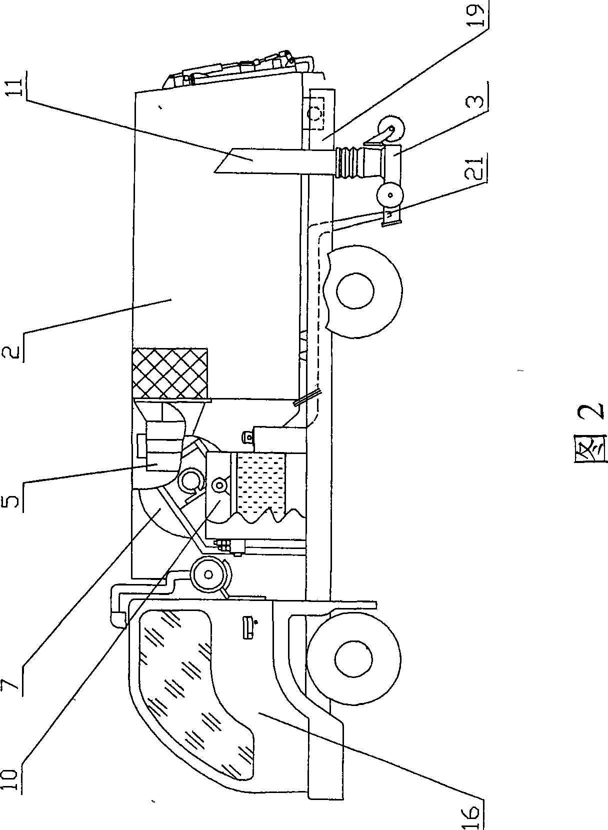
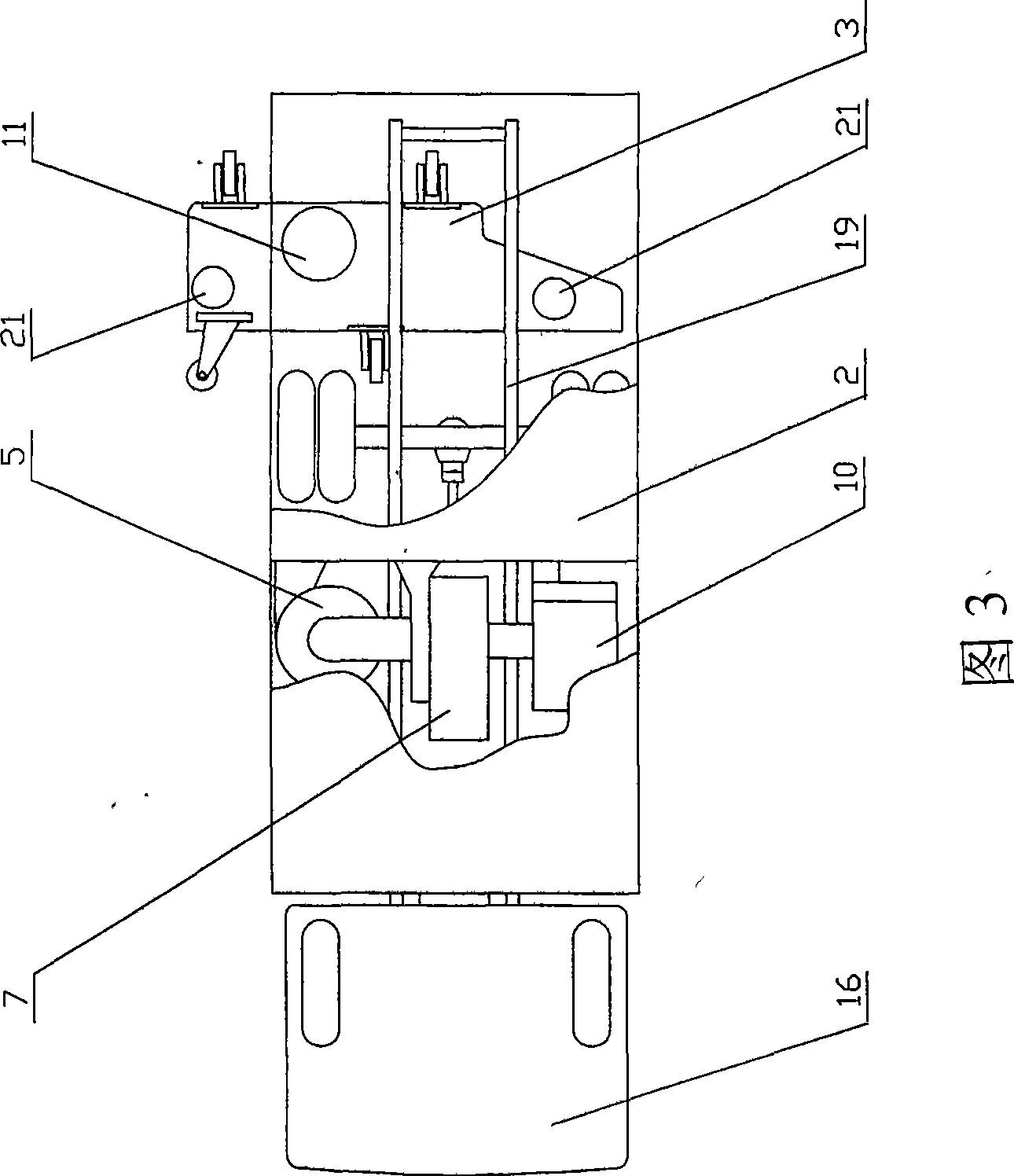
[0050] The second embodiment, the second embodiment is an expansion on the basis of the compound transmission structure of the first embodiment, it is a compound transmission sanitation cleaning vehicle that works in a dry dust filtration mode, as shown in Figure 2 and Figure 3 . Fig. 2 is a schematic diagram of the structure of the dust suction and sanitation cleaning vehicle of the second embodiment, and Fig. 3 is a schematic top view of Fig. 2 .

[0051] On the basis of the compound transmission structure of the first embodiment, a suction cup 3 is installed on the vehicle frame 19, and a suction cylinder 11 is installed on the suction cup 3 to communicate with the garbage bin 2; a cyclone separator 5 is installed on the vehicle frame 19, so that The air inlet of the cyclone separator 5 is connected to the dustbin 2, the air outlet of the air outlet is connected to the air inlet of the ventilator 7, the air inlet of the fan 7 is respectively connected to the air outlet of th...

no. 3 example

[0055]The third embodiment, the third embodiment is a compound drive sweeping and suction cleaning vehicle, which is an expansion on the basis of the transmission structure and dust suction operation structure of the first embodiment, as shown in Figure 4. Fig. 4 is a schematic structural diagram of a compound transmission sweeping, dust-absorbing and sanitation cleaning vehicle according to a third embodiment of the present invention.

[0056] On the basis of the compound transmission structure of the first embodiment, a suction cup 3 is installed on the vehicle frame 19, and a suction cylinder 11 is installed on the suction cup 3 to communicate with the dustbin 2, and the air inlet of the fan 7 is connected to the dustbin 2; The two sides of the vehicle frame 19 and the front of the suction cup 3 are respectively equipped with butterfly-shaped sweeping brushes 6, and the battery 14 is connected to the motor to drive the butterfly-shaped sweeping brushes 6 for cleaning operati...


PUM


Abstract

The invention relates to a compound-drive vacuum sweeper. The vacuum sweeper comprises an engine, a gear box, a silicon rectifying generator, a storage battery, a power converter and a motor A, which are all arranged on a chassis, wherein the engine drives a transmission shaft and a rear axle shaft through the gear box to drive the vacuum sweeper to run. The engine drives a power takeoff and the silicon rectifying generator through the gear box. The silicon rectifying generator is connected with the power converter and the storage battery to output generated electric current. The power converter is connected with the motor A which drives a fan and a water pump respectively. The fan sucks dust and garbage on the ground in front of a suction cup into a dustbin through the dustbin, a suction tube and the suction cup. The water pump pumps water from a water from a water tank to control dust by a wet method. The technology of the invention is applied to a special urban environment sanitary vehicle with vehicle-mounted operating devices, and the special vehicle has an oil-saving effect due to the use of a single engine as well as good operating effects. A compound drive system of compound-drive vacuum sweeper can generate electricity continuously and overcomes the drawback of short operating time of the electrical vehicle due to limitation from the capacity of the storage battery.

Description

technical field [0001] The invention relates to sanitation equipment, in particular to a compound transmission sanitation cleaning vehicle. Background technique [0002] At present, urban road cleaning has increasingly used mechanized equipment such as vacuum cleaners and sweepers. Two engines are installed on large and medium-sized vacuum cleaners and sweepers. The main engine is responsible for driving the vehicle, and the auxiliary engine is responsible for providing stable power to drive the vehicle-mounted operating device. On small vacuum cleaners and sweepers, due to the limited space of the vehicle, a single engine is generally used to drive multiple hydraulic pumps in series, and several hydraulic pumps drive hydraulic motors to drive the vehicle and work the working device. [0003] The fuel consumption of the power transmission system of the two engines is high, and the engines basically work in the low speed and high fuel consumption area, and generally there ar...

Claims


Application Information

Patent Timeline
IPC IPC(8): E01H1/08E01H1/04E01H1/05
Inventor 赵国贵赵宏坚
Owner 赵国贵
Why Eureka
Try Eureka