Photovoltaic device

A photovoltaic device and photovoltaic module technology, applied in the field of solar photovoltaics, can solve problems such as bracket processing errors, damage to the roof, and difficult installation of brackets, so as to reduce the pull-out force and offset force, facilitate and stabilize the installation, and secure the photovoltaic device. Effect

Active Publication Date: 2012-09-05
BOE TECH GRP CO LTD +1
View PDF4 Cites 28 Cited by
  • Summary
  • Abstract
  • Description
  • Claims
  • Application Information

AI Technical Summary

Problems solved by technology

[0003] In addition, ordinary photovoltaic devices installed with battery modules need to be able to withstand wind loads for 50 years, so prefabricated cement foundations are required, which will damage the original roof; cement foundations and roof waterproofing will increase the cost of photovoltaic systems ; In addition, the processing error and assembly error of the existing bracket will make it difficult to install the bracket
In addition, ordinary photovoltaic installations have a large counterweight and require high support capacity on the roof.

Method used


Image

  • Photovoltaic device
  • Photovoltaic device
  • Photovoltaic device

Examples


Embodiment Construction

[0033] Below in conjunction with accompanying drawing and embodiment, the specific embodiment of the present invention is described in further detail. The following examples are used to illustrate the present invention, but are not intended to limit the scope of the present invention.

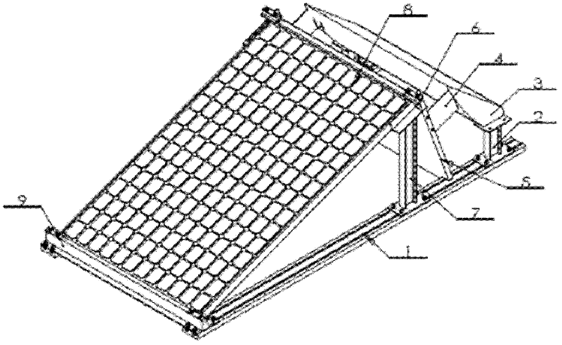
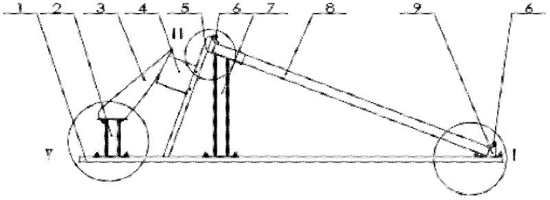
[0034] figure 2 shows a perspective view of the photovoltaic device of this embodiment, image 3 is its side view, Figure 4 is its top view, Figure 5 is its front view. The photovoltaic device as shown in the figure includes a photovoltaic module 8 arranged on the base 1 inclined from bottom to top in the direction from front to back. Deflector 5. The orientation words "upper", "lower", "front", and "rear" appearing hereinafter are all based on the above description.

[0035] In this embodiment, the base 1 includes two base plates arranged side by side at intervals, each base plate is provided with a guide rail, and the photovoltaic module 8 is installed on the guide rail, which is con...


PUM


Abstract

The invention discloses a photovoltaic device. The photovoltaic device comprises photovoltaic components which are obliquely arranged on a base from bottom to top, wherein the rear sides of the photovoltaic components are provided with deflectors which are obliquely arranged on the base from bottom to top in the direction from rear to front. According to the invention, the deflectors are designed to reduce the shape coefficient and pulling force when wind load acts; due to design of spoilers, the air flow speed is changed, downward pressure is generated, and the spoilers can play a role in increasing the weight and reduce the pulling force and the deviating force under the action of the wind load; due to design of the base consisting of guide rails and supporting columns thereon, the installation of the supported photovoltaic components, the deflectors and the spoilers is convenient and stable, and an arrayed whole body can be conveniently formed, so that photovoltaic device is firmer; and due to design of a clamping structure consisting of front supporting columns, rear supporting columns and pressing strips, the longitudinal gap is automatically made up in the clamping process of the photovoltaic components, and the components can be prevented from sliding out.

Description

technical field [0001] The invention relates to the field of solar photovoltaics, in particular to a photovoltaic device. Background technique [0002] Building energy conservation and photovoltaic power generation are the key development directions of the modern construction industry. Therefore, BIPV is a new technology with great potential and significant value. The photovoltaic power generation device on the roof of the building mainly includes battery components composed of solar cells and carriers. The battery components are installed on the roof facing the sun, and the solar cell components convert light energy into electrical energy, and collect the electrical energy and input it into the grid. There are many technical solutions, which belong to the relatively mature technology, and the general structure of the photovoltaic power generation device is as follows: figure 1 Shown, comprise column 31, beam 32 and ceiling 33, analysis bar 34 and grid 35 are installed on ...

Claims


Application Information

Patent Timeline
Patent Type & Authority Applications(China)
IPC IPC(8): H02N6/00H02S20/10H02S30/00
CPCY02E10/50Y02E10/47H02S20/00H02S20/24F24S40/53F24S40/85F24S25/30F24S25/13F24S2025/02Y02B10/10H01L31/042
Inventor 宋行宾杨培环
Owner BOE TECH GRP CO LTD
Why Eureka
Try Eureka