
Photonic lattice LEDs for ophthalmic illumination

A photonic lattice and ophthalmology technology, applied in the field of lighting, can solve the problems of unable to send light energy into low etendue optical fiber, low luminous power, etc.

Inactive Publication Date: 2012-09-05
ALCON RES LTD
View PDF9 Cites 4 Cited by
  • Summary
  • Abstract
  • Description
  • Claims
  • Application Information

AI Technical Summary

Problems solved by technology

Thus, due to the relatively high etendue of conventional LEDs and their relatively low luminous power, conventional LEDs may not be able to send sufficient light energy into low etendue fibers

Method used


Image

  • Photonic lattice LEDs for ophthalmic illumination
  • Photonic lattice LEDs for ophthalmic illumination
  • Photonic lattice LEDs for ophthalmic illumination

Examples


Embodiment Construction

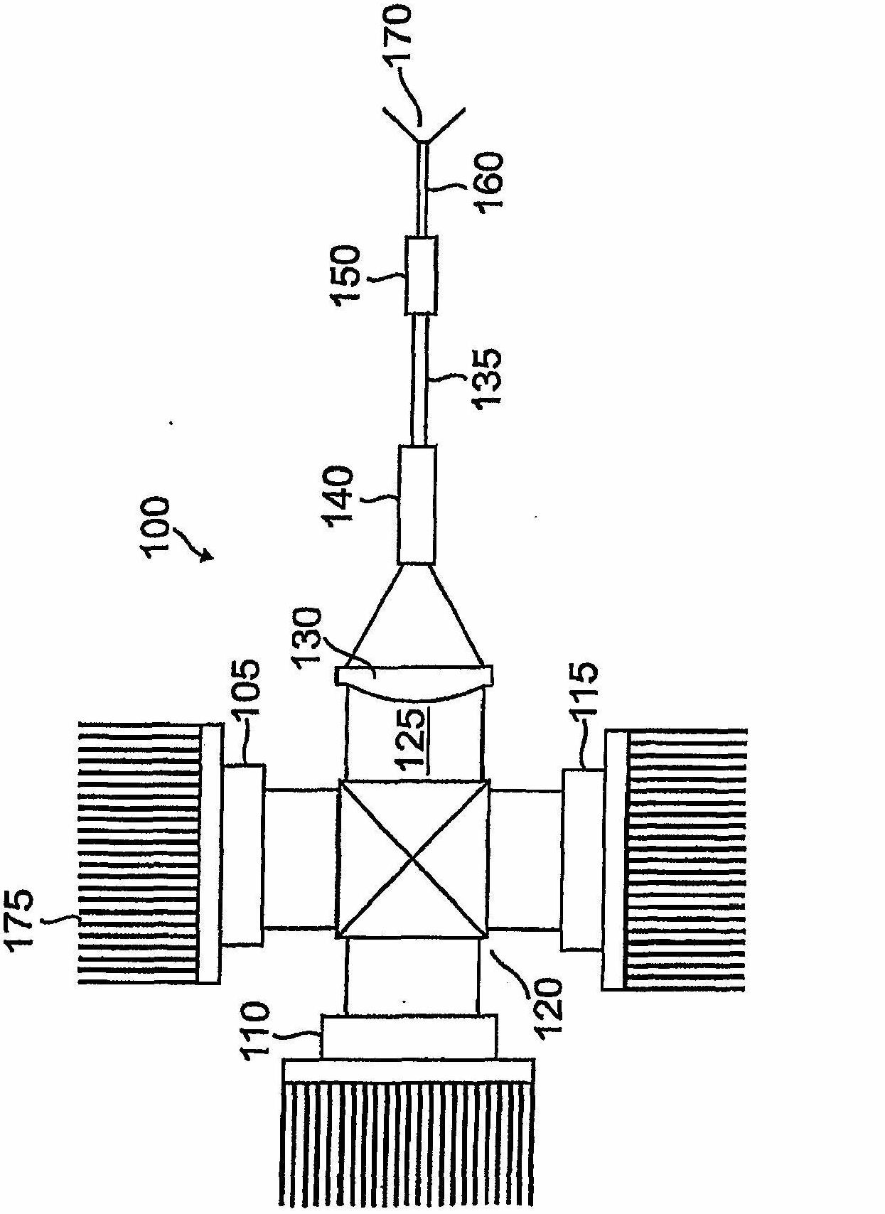
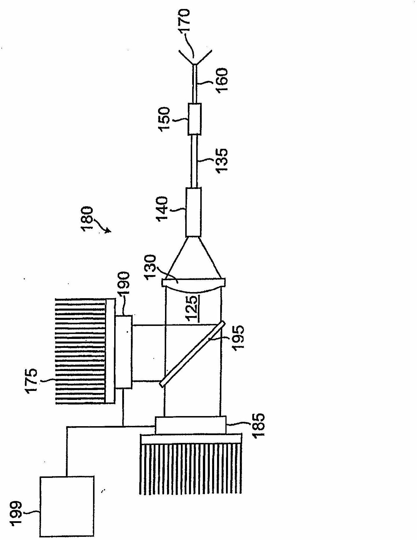
[0011] A class of LEDs known as photonic lattice light-emitting diodes (LEDs) is used to drive the optical fibers in the internal illuminator. Since photonic lattice LEDs are relatively low etendue sources, there is a high degree of efficiency. In this way, there is a sufficient degree of coupling of the light radiated by the photonic crystal LED into the optical fiber of the internal illuminator, thereby illuminating the intraocular surgical field with a sufficient level of lumens.

[0012] In contrast to photonic lattice LEDs, conventional LEDs emit light both normal and sideways relative to the LED surface. But the surface of a photonic lattice LED is patterned with sub-wavelength microstructures that self-collimate such that emission of side-guided light is minimized or eliminated. The lattice-like arrangement of microstructures in photonic lattice LEDs allows photons to exit the LED surface orthogonally and suppresses conventional lateral propagation. Thus, not only sh...


PUM


Abstract

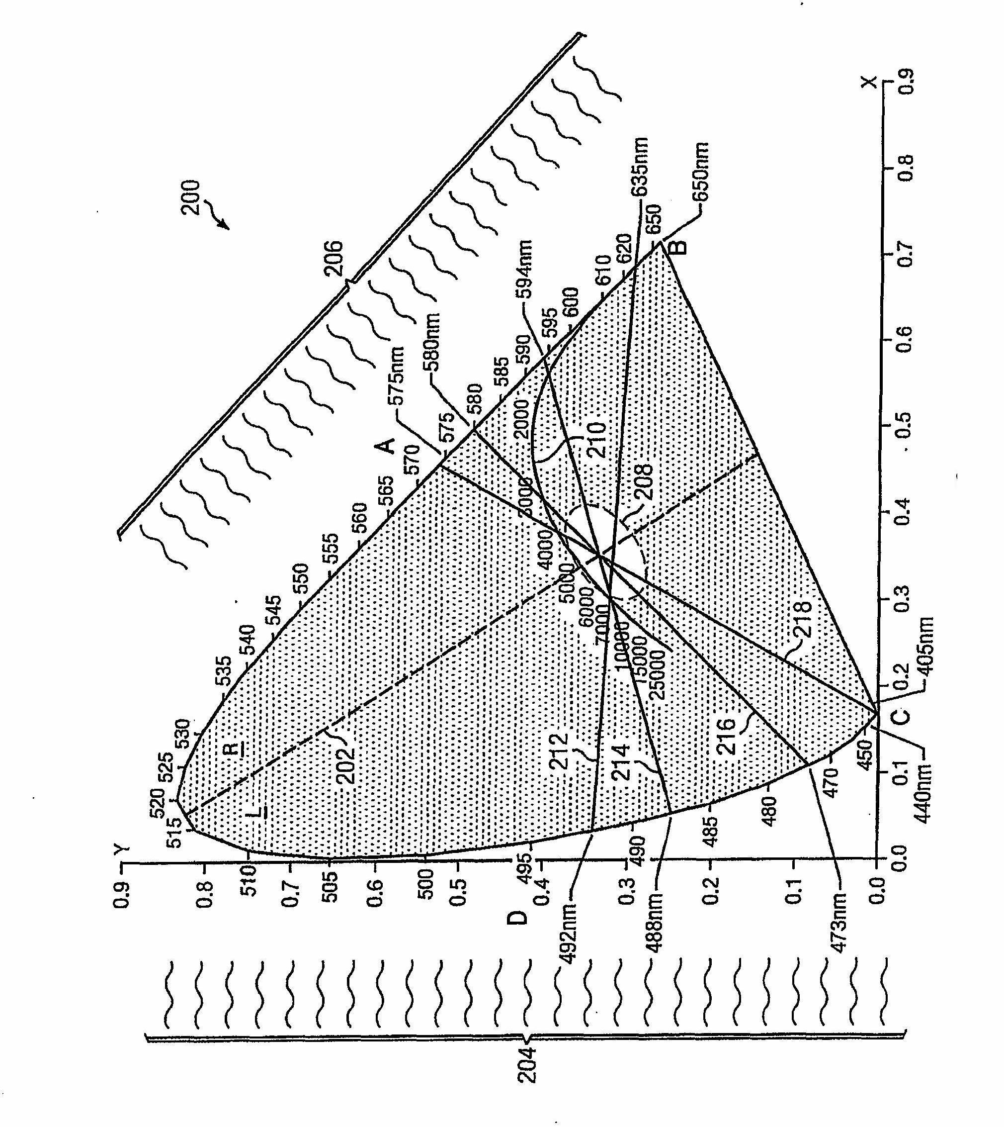
Photonic lattice sources drive an optical fiber in an ophthalmic illuminator to illuminate the interior of an eye. To produce white light, an RGB combination of photonic lattice LEDs may be used. Alternatively, a bichromatic combination of photonic lattice LEDs produces white light.

Description

technical field [0001] This application relates to illumination in ophthalmic procedures, and more particularly to ophthalmic illumination using photonic lattice light-emitting diodes (photonic lattice LEDs). Background technique [0002] Ophthalmic illuminators allow surgeons to illuminate the internal structures of the eye, such as the vitreous and retina, during surgical procedures. Endoscopic ophthalmic illuminators (internal illuminators) include optical fibers within the lumen of a cannula. By driving the proximal end of the fiber with a suitable light source, light emitted from the distal end of the fiber illuminates the desired portion of the eye. Modern minimally invasive techniques require relatively high gauge cannulas, such as 20 gauge (0.0295 inch diameter) or even higher gauge, such as 25 gauge. But the surgeon also needs enough luminous power from the internal illuminator to fully illuminate the surgical field within the eye. [0003] As described below, th...

Claims


Application Information

Patent Timeline
IPC IPC(8): A61B3/10
CPCA61B3/0008
Inventor A·阿尔茨尤霍维奇
Owner ALCON RES LTD
Learn More