
High-density patch-panel assemblies for optical fiber telecommunications

a technology patch panels, applied in the field of optical fiber telecommunications equipment and networks, can solve the problems of occupying relatively large space occupied by telecommunication equipment, space management, telecommunication equipment, etc., and achieves the effects of convenient use of rfid systems, high patch panel density, and convenient finger access

Active Publication Date: 2010-12-21
CORNING OPTICAL COMM LLC
View PDF135 Cites 232 Cited by
  • Summary
  • Abstract
  • Description
  • Claims
  • Application Information

AI Technical Summary

Benefits of technology

[0004]The present invention relates to patch panel assemblies that can support a relatively high density of patch panels. The patch panel assemblies have a configurations that takes advantage of cable fibers and jumper fibers that are bend-insensitive. The use of multiple rows of patch panel modules serves to distribute the density to enable ease of finger access to the modules, and facilitates the use of RFID systems that have difficulty reading densely packed RFID tags.

Problems solved by technology

A common problem in telecommunications systems, and in particular with optical telecommunications equipment, is space management.
This has resulted in telecommunications equipment that occupies relatively large amounts of space, and in particular a relatively large amount of floor space in a central office of a telecommunications network.
It has also lead to data center patch panels being increasingly overpopulated due to connector and cable volumes.

Method used


Image

  • High-density patch-panel assemblies for optical fiber telecommunications
  • High-density patch-panel assemblies for optical fiber telecommunications
  • High-density patch-panel assemblies for optical fiber telecommunications

Examples


Embodiment Construction

[0041]Reference is now made in detail to the present preferred embodiments of the invention, examples of which are illustrated in the accompanying drawings. Whenever possible, the same or similar reference numerals are used throughout the drawings to refer to the same or similar parts. It should be understood that the embodiments disclosed herein are merely examples, each incorporating certain benefits of the present invention. Various modifications and alterations may be made to the following examples within the scope of the present invention, and aspects of the different examples may be mixed in different ways to achieve yet further examples. Accordingly, the true scope of the invention is to be understood from the entirety of the present disclosure, in view of but not limited to the embodiments described herein.

[0042]Terms such as “horizontal,”“vertical,”“front,”“back,” etc., are used herein for the sake of reference in the drawings and ease of description and are not intended to...


PUM


Abstract

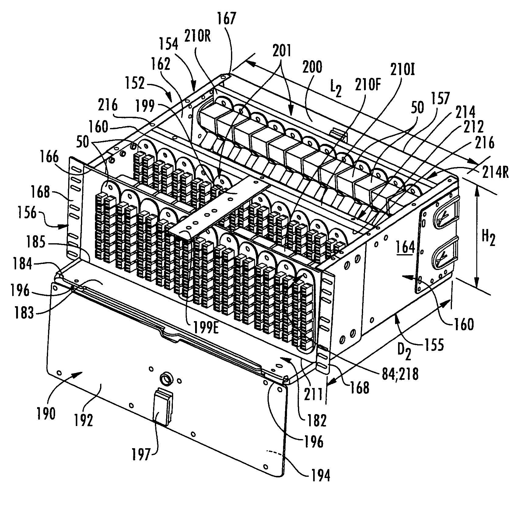
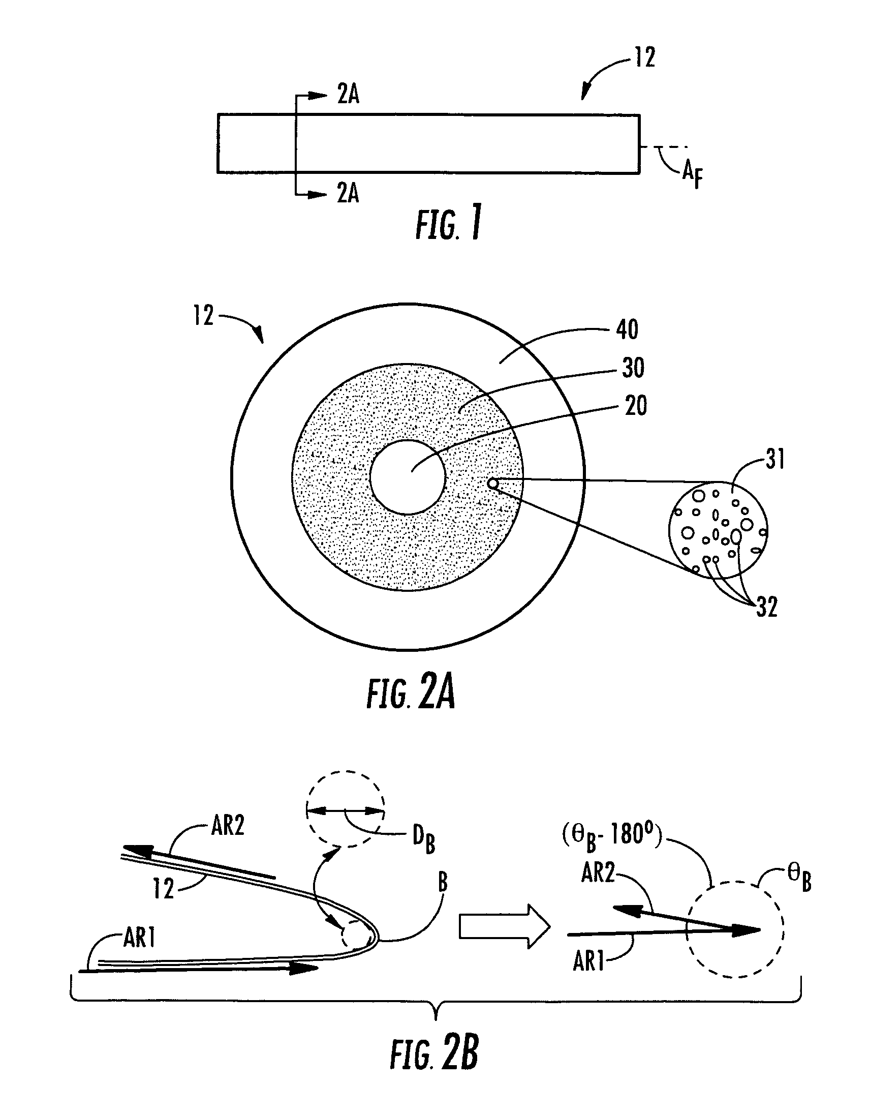
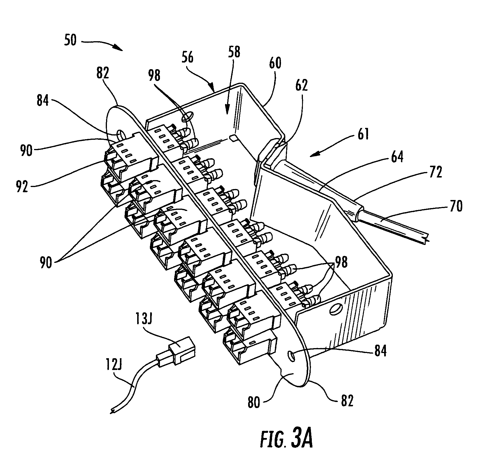
Patch panel assemblies (150) that contain patch panel modules (50) for use in optical fiber telecommunication systems are disclosed. One of the patch panel assemblies includes a front mounting frame (210F) and at least one internal mounting frame (210I) that support a plurality of patch panel modules. The patch panel assembly also includes a hinge assembly (224) configured allow bend-insensitive fiber cables (70) to be routed therethrough. One of the patch panel assemblies includes a housing (152) with a drawer (270) that supports a plurality of patch panel modules. The patch panel modules employ bend-insensitive optical fibers (12C) to connect front and rear ports (92, 98) so that the patch panels have a reduced size as compared to conventional patch panel modules. The patch panel assemblies include a cable distribution box (300) that can store excess cable and that assists in routing bend-insensitive fiber optic cables within the patch panel assembly interior (200) in order to connect to select patch panel module jacks (90).

Description

FIELD OF THE INVENTION[0001]The present invention relates generally to optical fiber telecommunications equipment and networks, and in particular relates to patch panel assemblies that can contain a relatively high density of patch panel modules.BACKGROUND OF THE INVENTION[0002]Typical optical telecommunication systems and networks include one or more telecommunications data centers that provide large numbers of optical and electrical cable connections that join various types of network equipment. The typical system also includes a number of outlying stations that extend the system into a network. Examples of network equipment include electrically-powered (active) units such as optical line terminals (OLTs), optical network terminals (ONTs), network interface devices (NIDs), servers, splitters, combiners, multiplexers, switches and routers, fanout boxes and patch panels. This network equipment is often installed within cabinets in standard-sized equipment racks. Each piece of equipm...

Claims


Application Information

Patent Timeline
Patent Type & Authority Patents(United States)
IPC IPC(8): G02B6/00
CPCG02B6/4452G02B6/02342G02B6/3897
Inventor BIRIBUZE, ERICLEWALLEN, CHRISTOPHER P.LUTHER, JAMES P.MCGRANAHAN, DANIEL S.ISENHOUR, MICAH C.
Owner CORNING OPTICAL COMM LLC
Learn More