Ytterbium-doped optical fiber, fiber laser, and fiber amplifier

a technology of ytterbium-doped optical fiber and fiber laser, which is applied in the direction of polarised optical fiber, clad optical fiber, instruments, etc., can solve the problems of non-uniform concentration distribution, limited amplification power, and likely to induce damage in the core glass or a nonlinear optical phenomenon, etc., to achieve superior optical amplification, inexpensively provide a fiber laser, and large quantity

Active Publication Date: 2013-01-29
FUJIKURA LTD
View PDF31 Cites 220 Cited by
  • Summary
  • Abstract
  • Description
  • Claims
  • Application Information

AI Technical Summary

Benefits of technology

[0046]According the ytterbium-doped optical fiber according to either one of (1) and (2), it is possible to inexpensively provide a large quantity of an optical fiber in which photodarkening is suppressed and a superior optical amplification can be obtained. Moreover, by using this type of optical fiber as an optical amplification medium, it is possible to inexpensively provide a fiber laser and a fiber amplifier in which a reduction in output power, which emerges over time, can be suppressed, and the optical characteristic thereof is superior.

Problems solved by technology

However, it may have a non-uniform concentration distribution of Yb, and furthermore, it may be doped to a part of the cladding 112.
As a result, it is likely to induce damage in the core glass or a nonlinear optical phenomenon.
Alternatively, amplification power becomes restricted.
This increased loss causes the gradually degradation of the optical amplification efficiency of the rare earth-doped optical fiber, which is an optical amplification medium, over time.
As a result, output of the fiber amplifier and fiber laser becomes lower over time, and the lifetime thereof becomes shorter.

Method used


Image

  • Ytterbium-doped optical fiber, fiber laser, and fiber amplifier
  • Ytterbium-doped optical fiber, fiber laser, and fiber amplifier
  • Ytterbium-doped optical fiber, fiber laser, and fiber amplifier

Examples


example 1

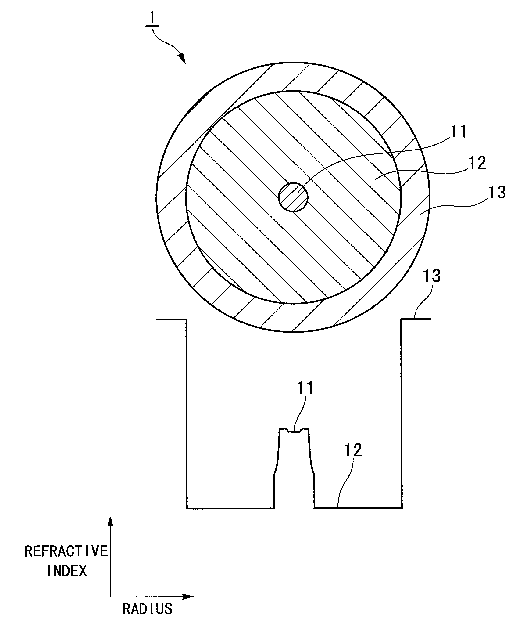
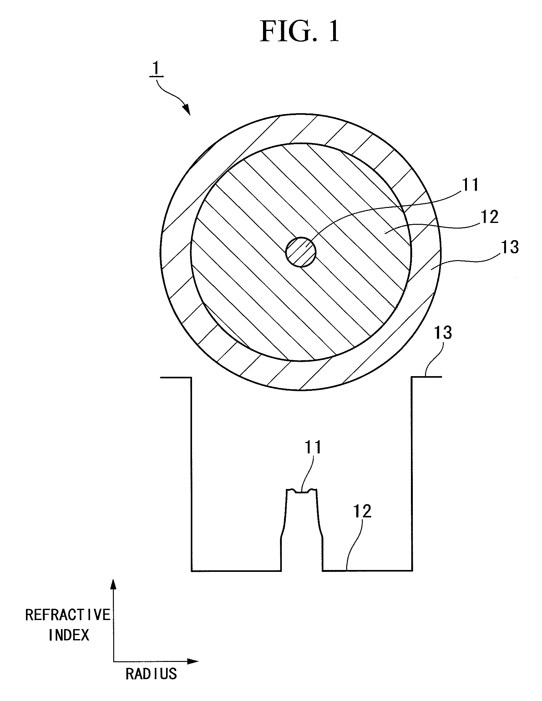
[0121]A Yb-doped optical fiber of the structure shown in FIG. 1 was fabricated. FIG. 1 is a drawing showing a cross-section of a Yb-doped optical fiber 1 and the refractive index profile thereof, the cross-section being parallel to the radial direction. The Yb-doped optical fiber 1 is a single-cladding fiber in which a cladding 12 is arranged on the outer periphery of a core 11, and a protective coating layer 13 is arranged on the outer periphery of the cladding 12.

[0122]A fiber preform was fabricated by MCVD method. Moreover, Yb was doped by solution method. The fiber preform was drawn until the glass outer diameter became approximately 125 μm, and the protective coating layer was arranged on the outer periphery thereof.

[0123]Yb2O3 in the core was 0.46 mole percent, P2O5 / Yb2O3 was 6.61, Al2O3 / Yb2O3 was 15.92, and Al2O3 / P2O5 was 2.41. Moreover, the relative refractive index difference (Δ) of the core was 0.29%.

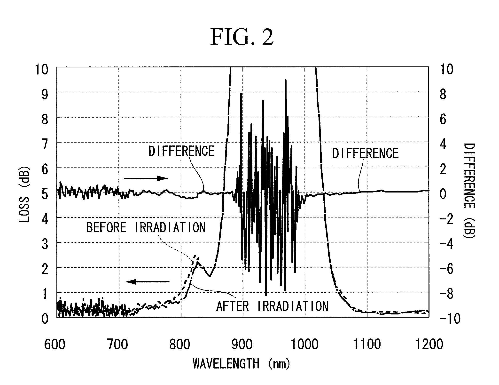
[0124]Almost no increase was found in loss caused by photodarkening in th...

example 2

[0127]A Yb-doped optical fiber of the structure shown in FIG. 3 was fabricated. FIG. 3 is a drawing showing a cross-section of a Yb-doped optical fiber 2 and the refractive index profile thereof, the cross-section being parallel to the radial direction. The Yb-doped optical fiber 2 is a single-cladding fiber in which a cladding 22 is arranged on the outer periphery of a core 21, and a protective coating layer 23 is arranged on the outer periphery of the cladding 22.

[0128]A fiber preform was fabricated by VAD method. Moreover, Yb was doped by solution method. The fiber preform was drawn until the glass outer diameter became approximately 125 μm, and the protective coating layer was arranged on the outer periphery thereof.

[0129]Yb2O3 in the core was 0.38 mole percent, P2O5 / Yb2O3 was 29.71, Al2O3 / Yb2O3 was 31.06, and Al2O3 / P2O5 was 1.05. Moreover, the relative refractive index difference (Δ) of the core was 0.14%.

[0130]Almost no increase was found in loss caused by photodarkening in th...

example 3

[0133]A Yb-doped optical fiber of the structure shown in FIG. 4 was fabricated. FIG. 4 is a drawing showing a cross-section of a Yb-doped optical fiber 3 and the refractive index profile thereof, the cross-section being parallel to the radial direction. The Yb-doped optical fiber 3 is a single-cladding fiber having a core 31 of a three-layer structure, in which a cladding 32 is arranged on the outer periphery of a core 31, and a protective coating layer 33 is arranged on the outer periphery of the cladding 32. The core 31 includes a center core 31a, a ring groove 31b arranged on the outer periphery of the center core 31a, and a ring core 31c arranged on the outer periphery of the ring groove 31b.

[0134]A fiber preform was fabricated by MCVD method. Moreover, Yb was doped by means of solution method. The fiber preform was drawn until the glass outer diameter became approximately 125 μm, and the protective coating layer was arranged on the outer periphery thereof.

[0135]Yb2O3 in the co...


PUM

PropertyMeasurementUnit
oscillating wavelengthaaaaaaaaaa
diameteraaaaaaaaaa
diameteraaaaaaaaaa

Abstract

An ytterbium-doped optical fiber of the present invention includes: a core which contains ytterbium, aluminum, and phosphorus and does not contain germanium; and a cladding which surrounds this core. The ytterbium concentration in the core in terms of ytterbium oxide is 0.09 to 0.68 mole percent. The molar ratio between the phosphorus concentration in the core in terms of diphosphorus pentoxide and the above ytterbium concentration in terms of ytterbium oxide is 3 to 30. The molar ratio between the aluminum concentration in the core in terms of aluminum oxide and the above ytterbium concentration in terms of ytterbium oxide is 3 to 32. The molar ratio between the above aluminum concentration in terms of aluminum oxide and the above phosphorus concentration in terms of diphosphorus pentoxide is 1 to 2.5.

Description

CROSS-REFERENCE TO RELATED APPLICATION[0001]This application is a continuation application based on a PCT Patent Application No. PCT / JP2009 / 006136, filed Nov. 16, 2009, whose priority is claimed on Japanese Patent Application No. 2008-292013, filed Nov. 14, 2008, the entire content of which are hereby incorporated by reference.BACKGROUND OF THE INVENTION[0002]The present invention relates to an ytterbium-doped optical fiber in which photodarkening is suppressed, and a fiber laser and a fiber amplifier respectively having the optical fiber.BACKGROUND ART[0003]Within an optical fiber having a rare earth element doped thereto, if pumping light is incident to this rare earth doped fiber, a population inversion is formed in the fiber. As a result, stimulated emission light of a wavelength corresponding to the wavelength of this pumping light is generated. Consequently, rare earth doped optical fiber of this type is widely used in fiber amplifiers which amplify signal light of a wavelengt...

Claims


Application Information

Patent Timeline
Patent Type & Authority Patents(United States)
IPC IPC(8): H01S3/067C03C13/04C03C3/04G02B6/02C03C4/08
CPCC03C3/06C03C13/045G02B6/024G02B6/036G02B6/03605H01S3/06716H01S3/1693C03C2201/10C03C2201/12C03C2201/14C03C2201/28C03C2201/31C03C2201/3488C03C2201/36G02B6/03633G02B6/03638G02B6/03644G02B6/03661H01S3/06712H01S3/06729H01S3/0675H01S3/094007H01S3/1618H01S3/1691H01S3/1608
Inventor NAKAGUMA, TERUNOICHII, KENTAROTANIGAWA, SHOJI
Owner FUJIKURA LTD
Why Eureka
Try Eureka