Drive train for a motor vehicle comprising an electric machine

a technology of electric machines and drive trains, which is applied in the direction of electric devices, battery/fuel cell control arrangements, capacitor propulsion, etc., can solve the problems of affecting the operation of the electric machine, the installation space requirement of such short and thick electric machines is a real disadvantage, and the electric machine becomes relatively large in the axial direction, so as to prevent the mechanical damage of the capacitor and ensure the effect of cooling of the stator

Inactive Publication Date: 2007-12-13
DAIMLER AG
View PDF2 Cites 62 Cited by
  • Summary
  • Abstract
  • Description
  • Claims
  • Application Information

AI Technical Summary

Benefits of technology

[0013] Integration both of the electric machine into the converter bell and of the power electronics and the capacitor into the electric machine forms a very compact electric drive module in the drive train. For this purpose, firstly common cooling of the stator, capacitor and power electronics is an important feature in the establishment of such a compact electric machine. Secondly, the arrangement of the power electronics and the capacitor in the radial direction around the stator or the cooling system of the stator primarily plays a critical role since, in this way, is it possible to provide an electric machine which is sufficiently compact to be accommodated in the space available, particularly in an axial direction.
[0027] A polygonal region is preferably provided next to the capacitor, which itself is likewise polygonal, preferably in the form of a ring, and which enables the components of the power electronics to be fitted on flat surfaces. Therefore, contact can be made with the stator or the cooling system of the stator over a large area, and effective cooling of said stator can therefore be ensured. A further advantage of the polygonal region is that a modular design with identical modules of the power electronics can be achieved. Adapting to the size and / or power of the electric machine is then carried out solely by selecting the number of sections, for example hexagonal, octagonal or dodecagonal. The same modules of the power electronics can then in each case be installed on the flat surfaces of the individual sections or of at least some of the sections independently of the size of the electric machine. As in every other type of modular construction, advantages in terms of flexibility are also produced here. Furthermore, identical modules can be used for electric machines of different sizes, which in turn reduces the costs of such a module as larger quantities of identical modules are produced.

Problems solved by technology

However, connecting the power electronics to the stator or to the cooling system of said stator in the axial direction of the electric machine means said electric machine becomes relatively large in the axial direction and requires a great deal of installation space.
The installation space requirement of such short and thick electric machines constitutes a real disadvantage in hybrid drives in particular.
However, at least in the case of relatively small electric machines, the problem arises that the power electronics are typically designed to be flat and not rounded.
As the size of the electric machine decreases, the contact area between the power electronics and stator and thus the cooling system also decreases and the heat transfer is detrimentally affected thereby.
In addition, the ring-like capacitor is likewise subjected to very severe thermal loads as the electric machine is heating up during operation.
Furthermore, the expansion of the capacitor, which typically manifests itself as an extension in the direction of the circumference of said capacitor, may adversely affect or completely destroy contact with the cooling system of the stator.
The capacitor, which is therefore no longer cooled or only poorly cooled, consequently overheats quickly, which further impairs contact.
This may ultimately lead to the capacitor breaking down since it will become too hot.
The problem in that case is that an intermediate-circuit capacitor still has to be arranged outside the electric machine.
However, the inductions which are inherent to the line elements for connection of said intermediate-circuit capacitor lead to considerable problems with voltage peaks which can very easily damage the components of the power electronics, and particularly the semiconductor switching elements in this case.

Method used


Image

  • Drive train for a motor vehicle comprising an electric machine
  • Drive train for a motor vehicle comprising an electric machine
  • Drive train for a motor vehicle comprising an electric machine

Examples


Embodiment Construction

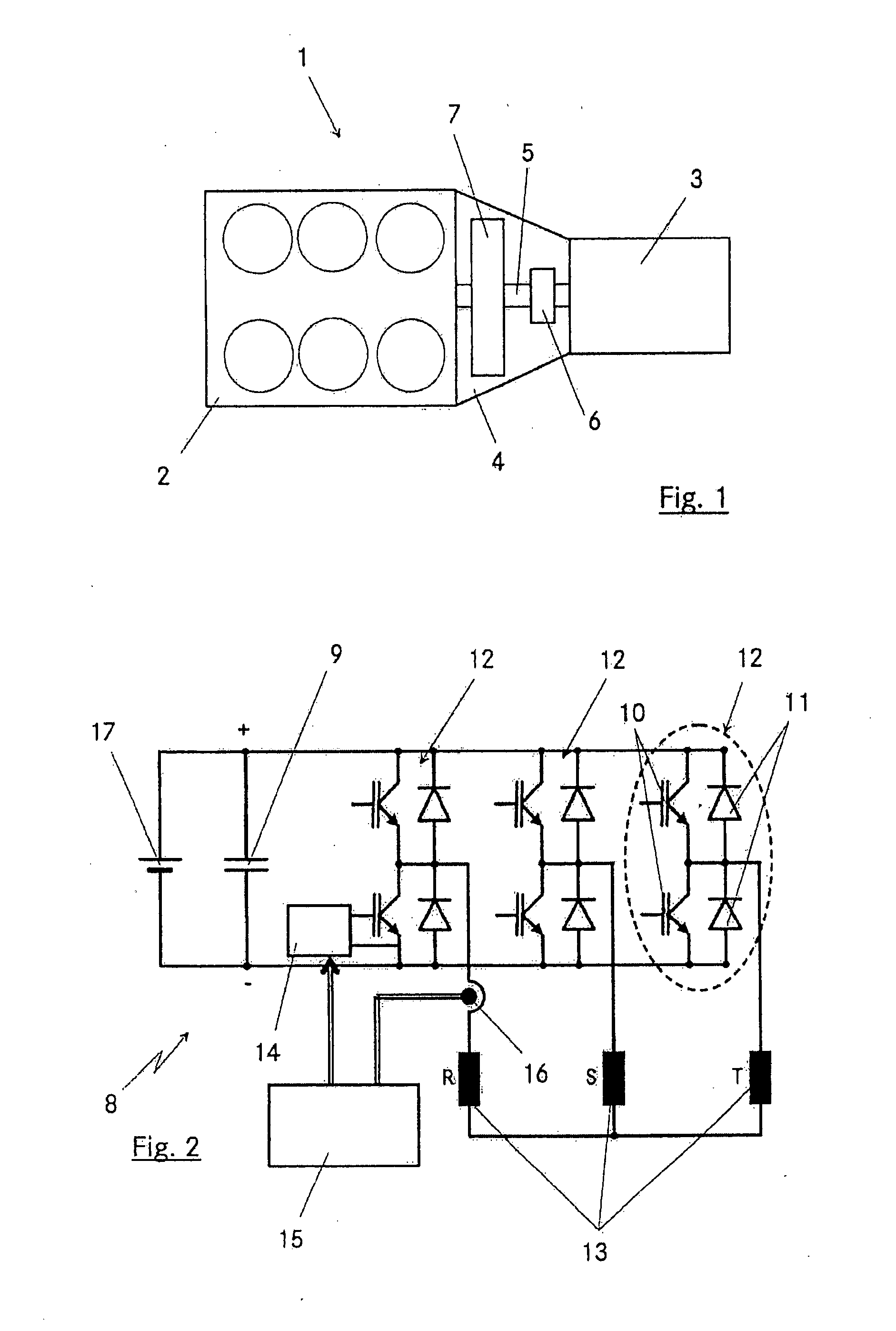
[0042]FIG. 1 shows a schematic plan view of a detail of a drive train 1. The main part of said drive train comprises an internal combustion engine 2 and a transmission 3. A converter bell 4, in which a drive shaft 5 for driving the transmission 3 using the internal combustion engine 2 extends, is arranged between the internal combustion engine and the transmission. As is generally customary, a clutch device 6 for interrupting the connection between the internal combustion engine 2 and the transmission 3 is also arranged in the converter bell 4. In addition, an electric machine 7 is arranged in the converter bell 4. In its drive mode, the electric machine can be used to drive the vehicle, which is provided with the drive train 1. In a generator mode, for example when the vehicle is decelerating, the electric machine 7 can generate electrical energy and feed it back to a suitable storage device, for example a battery and / or a high-power capacitor (supercap). A drive train 1 of this ty...


PUM


Abstract

In a drive train for a motor vehicle, with a converter bell arranged between an internal combustion engine and a transmission, and a drive shaft extending through the converter bell and carrying a clutch device and an electric machine together with a power converter, which comprises at least one capacitor and power electronics which are integrated into the converter bell, the capacitor and the power electronics are arranged between a stator of the electric machine and the converter bell such that they are distributed around the outer circumference of the electric machine in the radial direction and the capacitor and the power electronics are arranged such that they are in thermally conductive contact with the cooling system for the stator of the electric machine.

Description

[0001] This is a Continuation-in-Part Application of pending International Patent Application PCT / EP2005 / 010615 filed Oct. 1, 2005 and claiming the priority of German Patent Application 10 2004 048 908.4 filed Oct. 6, 2004.BACKGROUND OF THE INVENTION [0002] The invention relates to a drive train for a motor vehicle comprising an electric machine disposed between an internal combustion engine and a transmission and also to an electric machine for driving a motor vehicle, especially a so-called hybrid motor vehicle. [0003] A drive train of this generic type is described by Y. Tadros et al. in “Ring Shaped Motor-Integrated Electric Drive for Hybrid Electric Vehicles”, 10th European Conference on Power Electronics and Applications; Toulouse, 2003. In that publication, an electric machine is integrated in a converter bell between the internal combustion engine and transmission next to a clutch. The electric machine of this type, which can be designed in accordance with DE 102 07 486 A1, ...

Claims


Application Information

Patent Timeline
Patent Type & Authority Applications(United States)
IPC IPC(8): B60K8/00
CPCH02K7/006H02K11/0094H02K11/048H01L2224/48091H01L2224/48472H01L2924/00014H01L2924/00B60L3/0061B60L15/007B60L2210/40B60L2240/36Y02T10/70B60L50/40B60L50/16B60L58/26B60L58/40Y02T10/64Y02T10/72Y02T10/7072H02K11/05Y02T90/40
Inventor HELLER, MARCUSRENNEBERG, JENSROLLE, SVENSCHWIENBACHER, WOLFGANGTADROS, YEHIA
Owner DAIMLER AG
Why Eureka
Try Eureka