Auxiliary device for performing manual work

An auxiliary device and working technology, applied in the direction of manufacturing tools, metal processing equipment, metal processing machinery parts, etc., can solve the problem of falling and trapping, and achieve the effect of easy manipulation, simple structure and good connection

Inactive Publication Date: 2012-09-05
ROBERT BOSCH GMBH
View PDF9 Cites 4 Cited by
  • Summary
  • Abstract
  • Description
  • Claims
  • Application Information

AI Technical Summary

Problems solved by technology

Especially when opening a borehole in a wall, it is almost unavoidable in such a device that the drill cuttings trapped in the shell at first are removed after the drilling tool is pulled out of the borehole and associated therewith from the wall. Partially falls out when shells are captured and accordingly must be specifically captured

Method used


Image

  • Auxiliary device for performing manual work
  • Auxiliary device for performing manual work
  • Auxiliary device for performing manual work

Examples


Embodiment Construction

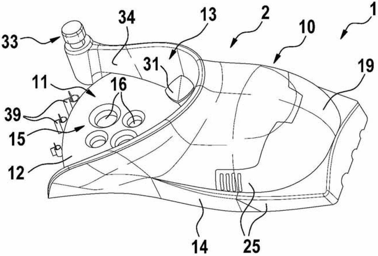
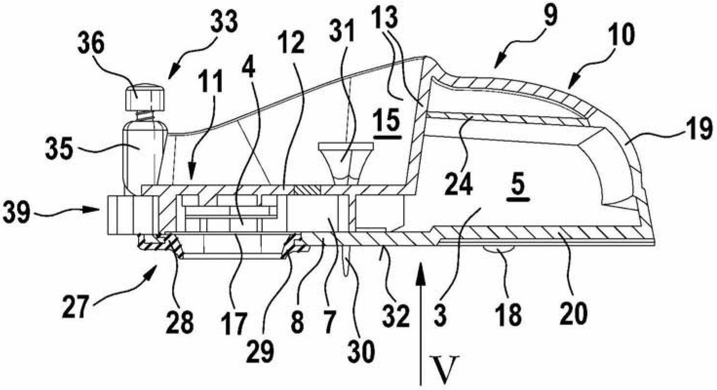
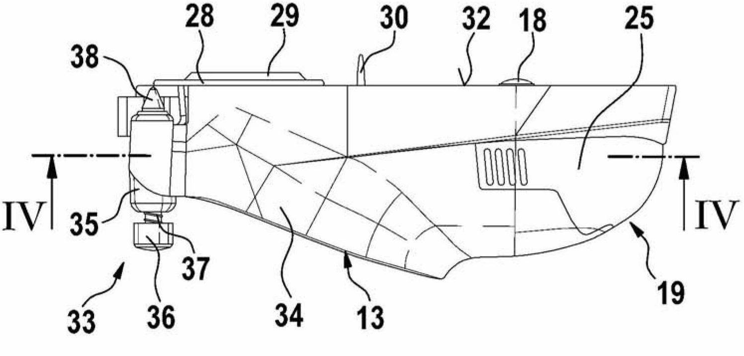
[0025] exist Figures 1 to 8 shows an auxiliary device 1 for performing manual work, which in its basic function forms a cuttings collection box 2 and in this respect encloses a collection chamber 3 with a working application not shown There is a catch chamber 4 through which the drilled tool emerges, and a collection container 5 which sinks relative to the catch chamber 4 and is connected to the catch chamber.

[0026] With respect to the collection box 2, which is elongated in its shape and shaped approximately like a mouse so that it can be handled easily, the capture chamber 4 and the collection container 5 lie opposite each other in the direction of the longitudinal axis 6 of the cuttings collection box 2, exactly Said to be connected via a short channel-like intermediate piece 7 . The collection container 5 is designed like a drawer and is inserted from behind in the direction of the longitudinal axis 6 into the collection box 2 , which has a housing 9 covering its bott...


PUM


Abstract

The invention relates to an auxiliary device for performing manual work, designed as a multi-functional auxiliary device (1) that in the basic function thereof is a drill cuttings collection box (2) having a catching chamber (4) and a collection container (5) separate from the catching chamber.

Description

technical field [0001] The invention relates to an auxiliary device for performing manual work according to the preamble of claim 1 . Background technique [0002] Auxiliary devices for capturing drilling dust or cuttings are designed, for example, as an attachment for suctioning dust (DE 195 43 599 B4) and as a jaw-shaped capture funnel, which is laterally, relative to the drilling or drilling tool, Parts are placed peripherally on the wall or ceiling side and are also fastened adhesively if necessary. The use of such additional devices is therefore subject to expenditure in acquisition and use, as they largely only work in the area of ​​the profile. [0003] In contrast to this, a really simple auxiliary device for capturing drilling cuttings or drilling dust is known from DE 20 2004 002 220 U1. The device is designed as an envelope-like container with its front side facing the wall, the container being on the side of the wall in the area where the drilled hole is to be ...

Claims


Application Information

Patent Timeline
Patent Type & Authority Applications(China)
IPC IPC(8): B23Q11/00
CPCB23Q11/0053B23Q11/0071
Inventor R·富克斯
Owner ROBERT BOSCH GMBH
Why Eureka
Try Eureka