Laser cutting machine

A laser cutting machine, laser technology, used in laser welding equipment, welding equipment, metal processing equipment and other directions, can solve the problems of lack of rigidity of steel plates, inconvenience to cut steel plates separately, and inability to easily replace stencils, etc., to meet the requirements of cutting Operation, the effect of good transmission accuracy

Inactive Publication Date: 2012-09-12
江苏大华激光科技开发有限公司
View PDF6 Cites 1 Cited by
  • Summary
  • Abstract
  • Description
  • Claims
  • Application Information

AI Technical Summary

Problems solved by technology

[0002] When laser cutting the steel plate material, the steel plate needs to be placed on the cutting screen when loading the material. Since the steel plate is heavy, there are support points at the grid nodes of the steel plate cutting screen, thereby reducing the distance between the steel plate and the cutting screen. Friction resistance makes feeding more convenient. However, soft materials such as cloth do not have the rigidity of the steel plate when cutting, so they cannot be placed flat on the above-mentioned cutting screen, so it is necessary to replace the ordinary screen before cutting.
The screen plate of the existing cutting machine cannot be easily replaced, so it is not convenient to cut soft materials such as steel plate and cloth separately

Method used


Image

  • Laser cutting machine
  • Laser cutting machine

Examples


Embodiment Construction

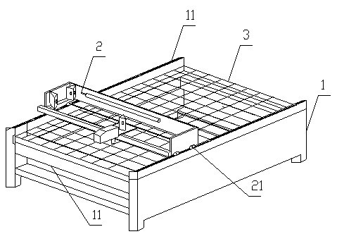
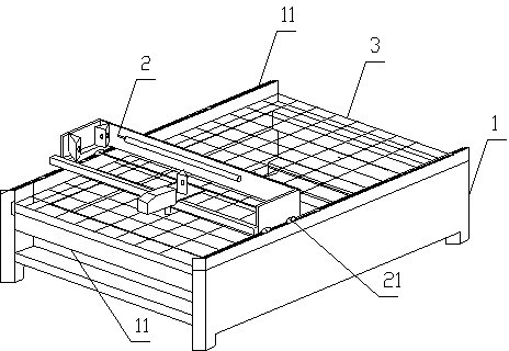
[0011] The present invention will be further described below in conjunction with the accompanying drawings and specific embodiments.

[0012] The laser cutting machine includes a frame 1, a laser horizontal frame 2 and a cutting screen 3, and the cutting screen 3 is slidably arranged on the frame 1 through slide rails arranged on the frame. The cutting screen 3 is a steel plate cutting screen or a cloth cutting screen. Wherein, support points (not shown in the figure) are provided at the grid nodes of the steel plate cutting stencil. Both sides of the frame 1 are provided with transmission racks 11, and the laser horizontal frame 2 is provided with a gear 21 meshing with the transmission racks. The middle part of the frame 1 is provided with a plurality of reinforcing rods 12 .

[0013] In the present invention, the cutting screen is slidably arranged on the frame, which is convenient for its extraction and replacement, thus meeting the different needs of cutting steel plate...


PUM


Abstract

The invention relates to a laser cutting machine. The laser cutting machine comprises a frame, a laser cross beam and a cutting mesh plate, wherein the cutting mesh plate is arranged on the frame in a sliding manner through a sliding track arranged on the frame. The cutting mesh plate is a steel plate cutting mesh plate or a cloth cutting mesh plate, wherein support points are arranged at mesh nodes of the steel plate cutting mesh plate. Transmission racks are arranged on the two sides of the frame, and a gear meshed with the transmission racks is arranged on the laser cross beam. A plurality of reinforcing rods are arranged at the middle part of the frame. According to the laser cutting machine disclosed by the invention, the cutting mesh plate is arranged on the frame in the sliding manner for facilitating the drawing and replacement of the cutting mesh plate, so that the different needs for cutting steel plates and cloth can be met; simultaneously, the laser cross beam adopts rack-gear transmission, thereby having better transmission precision; and furthermore, the plurality of the reinforcing rods are arranged on the frame, thus the frame is more stable during cutting operation and the need of performing faster cutting operation can be further met.

Description

technical field [0001] The invention relates to a laser cutting machine. Background technique [0002] When laser cutting the steel plate material, the steel plate needs to be placed on the cutting screen when loading the material. Since the steel plate is heavy, there are support points at the grid nodes of the steel plate cutting screen, thereby reducing the distance between the steel plate and the cutting screen. Frictional resistance makes feeding more convenient. However, soft materials such as cloth do not have the rigidity of steel plates when cutting, so they cannot be placed flat on the above-mentioned cutting screen, so ordinary screens need to be replaced before cutting. The screen plate of the existing cutting machine cannot be easily replaced, so it is inconvenient to cut soft materials such as steel plate and cloth respectively. Contents of the invention [0003] The purpose of the present invention is to solve the above problems, and to provide a laser cutt...

Claims


Application Information

Patent Timeline
Patent Type & Authority Applications(China)
IPC IPC(8): B23K26/42B23K26/38B23K26/70
Inventor 彭良磊
Owner 江苏大华激光科技开发有限公司
Why Eureka
Try Eureka