
cutting tool

A technology of tools and pulleys, applied in the field of cutting tools, which can solve problems such as unstable cutting operations and high torque

Active Publication Date: 2020-11-20
KOKI HLDG CO LTD
View PDF13 Cites 0 Cited by
  • Summary
  • Abstract
  • Description
  • Claims
  • Application Information

AI Technical Summary

Problems solved by technology

In addition, especially in the third pulley, a large torque is applied along with the transmission of the rotation, so there is a problem that the cutting operation is unstable due to the occurrence of a gap in the rotation position and rotation transmission loss.

Method used


Image

  • cutting tool
  • cutting tool
  • cutting tool

Examples


Embodiment Construction

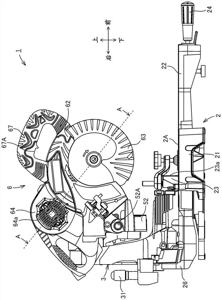
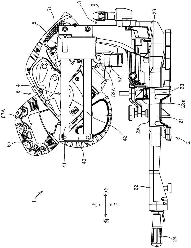
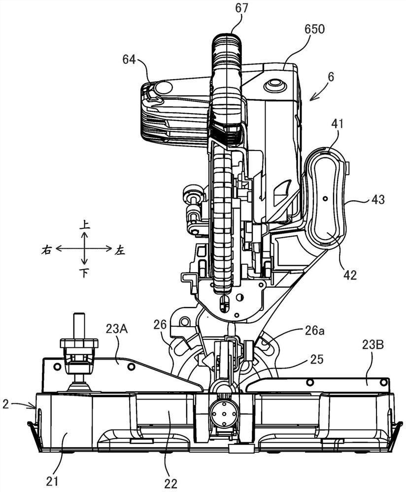
[0076] Hereinafter, embodiments of the present invention will be described with reference to the drawings. Here, a case where the present invention is applied to a table-type circular saw blade will be described as an example.

[0077] First, regarding the structure of the table circular saw blade according to the embodiment of the present invention, refer to Figure 1 to Figure 3 Be explained. figure 1 , figure 2 as well as image 3 These are a right side view, a left side view, and a front view showing the structure of the table-type circular saw blade 1 according to the embodiment of the present invention, respectively. Table circular saw blade 1 such as Figure 1 to Figure 3 As shown, it includes a base portion 2 having a mounting surface 2A, a bracket 3 , a guide portion 4 , a moving portion 5 , and a cutting portion 6 having a cutting blade 61 .

[0078] In the following description, the direction in which the guide portion 4 is installed with respect to the base p...


PUM


Abstract

The invention provides a cutting tool capable of positioning the third pulley with high precision. The desktop circular saw blade (1) has a first pulley (601) that rotates integrally with the motor shaft (68B), an intermediate shaft (602) that is provided with a second pulley (603) and a third pulley (605), and is mounted on the first pulley. (601) and the first transmission belt (604) between the second pulley (603), the main shaft (606) that is provided with the fourth pulley (607), erected between the third pulley (605) and the fourth pulley (607) The second transmission belt (608), the bearing (70a) that is located between the second pulley (603) and the third pulley (605) and rotatably supports the intermediate shaft (602), and the second pulley (605) that is located The pulley (603) is on the opposite side and rotatably supports the bearing (70b) of the intermediate shaft (602), the gear housing (65) supporting the bearings (70a, 70b) and the gear cover (66), and the gear housing (65) A part is located between the second pulley (603) and the third pulley (605).

Description

technical field [0001] The present invention relates to a cutting tool, and more particularly to a cutting tool for cutting a workpiece by rotating a cutting saw blade. Background technique [0002] Conventionally, a cutting tool such as a table circular saw is known that includes a motor, a plurality of pulleys, and transmits the rotation of the motor to a cutting saw blade through a belt stretched between the pulleys to cut a workpiece. [0003] In this cutting tool, through the first-stage transmission mechanism composed of the first pulley installed on the motor shaft, the second pulley installed on the intermediate shaft, and the first transmission belt installed between the first pulley and the second pulley, The rotational energy of the motor shaft is transmitted to the intermediate shaft. And, the rotation of the intermediate shaft is controlled by the second-stage transmission mechanism formed by the third pulley installed on the intermediate shaft, the fourth pull...

Claims


Application Information

Patent Timeline
Patent Type & Authority Patents(China)
IPC IPC(8): B23D47/12B23D45/04
CPCB23D45/048B23D47/12B23D45/046B23D45/14B23D47/02
Inventor 村上卓宏平野大关根凯尧岩田悟知
Owner KOKI HLDG CO LTD
Learn More