High-frequency magnetic material and antenna system using thereof

Active Publication Date: 2009-03-26
KK TOSHIBA
View PDF5 Cites 1 Cited by
  • Summary
  • Abstract
  • Description
  • Claims
  • Application Information

AI Technical Summary

Benefits of technology

[0010]A high-frequency magnetic material in an aspect of the present invention includes a substrate and a composite magnetic film formed on the substrate and made of a magnetic phase forming a plurality of columnar bodies whose longitudinal direction is directed in a direction perpendicular to a surface of the substrate and an insulator phase filling gaps of the columnar bodies, wherein the magnetic phase contains Fe and B (boron) and at least one of Nb, Zr, and Hf, and is amorphous, and has in-plane uniaxial anisotropy of Hk2/Hk1≧3 and Hk2≧3.98×10³ A/m when a minimal anisotropic magnetic field in a plane parallel to the surface of the substrate is Hk1 and a maximal anisotropic magnetic field is Hk2.
[0011]An antenna system in an aspect of the present invention includes a feed terminal, an antenna element whose one end is

Problems solved by technology

However, for example, if a metal is present near an antenna of a mobile device when the antenna radiates electromagnetic waves, radiation of electromagnetic waves is disturbed due to an induced current generated in the metal.
High permeability members of metal or alloy are not appropriate as high-frequency magnetic materials because transmission losses caused by an eddy current of radio waves become more pronounced as the frequency of radio waves increases.
Magnetic materials of oxide exemplified by ferrite, on the other hand, suppress transmission losses caused by an eddy current because of high resistivity, but the resonance frequencies are several hundred MHz and transmission losses caused by resonance in a high-frequency region higher than these frequencies become more pronounced and therefore, magnetic materials of oxide are not appropriate as high-frequency magnetic materials either.
However, with the granular structure, it is difficult to make permeability still higher by improving volume percentage of magnetic metal fine particles in a high-frequency magnetic material.
However, materials having the columnar structure have large magnetic anisotropic dispersion caused by a disturbance of crystalline orientation or the like and thus, there is a problem that a loss component μ″ in a high-frequency region is large and μ″ / μ′ is also large.

Method used


Image

  • High-frequency magnetic material and antenna system using thereof
  • High-frequency magnetic material and antenna system using thereof
  • High-frequency magnetic material and antenna system using thereof

Examples


first embodiment

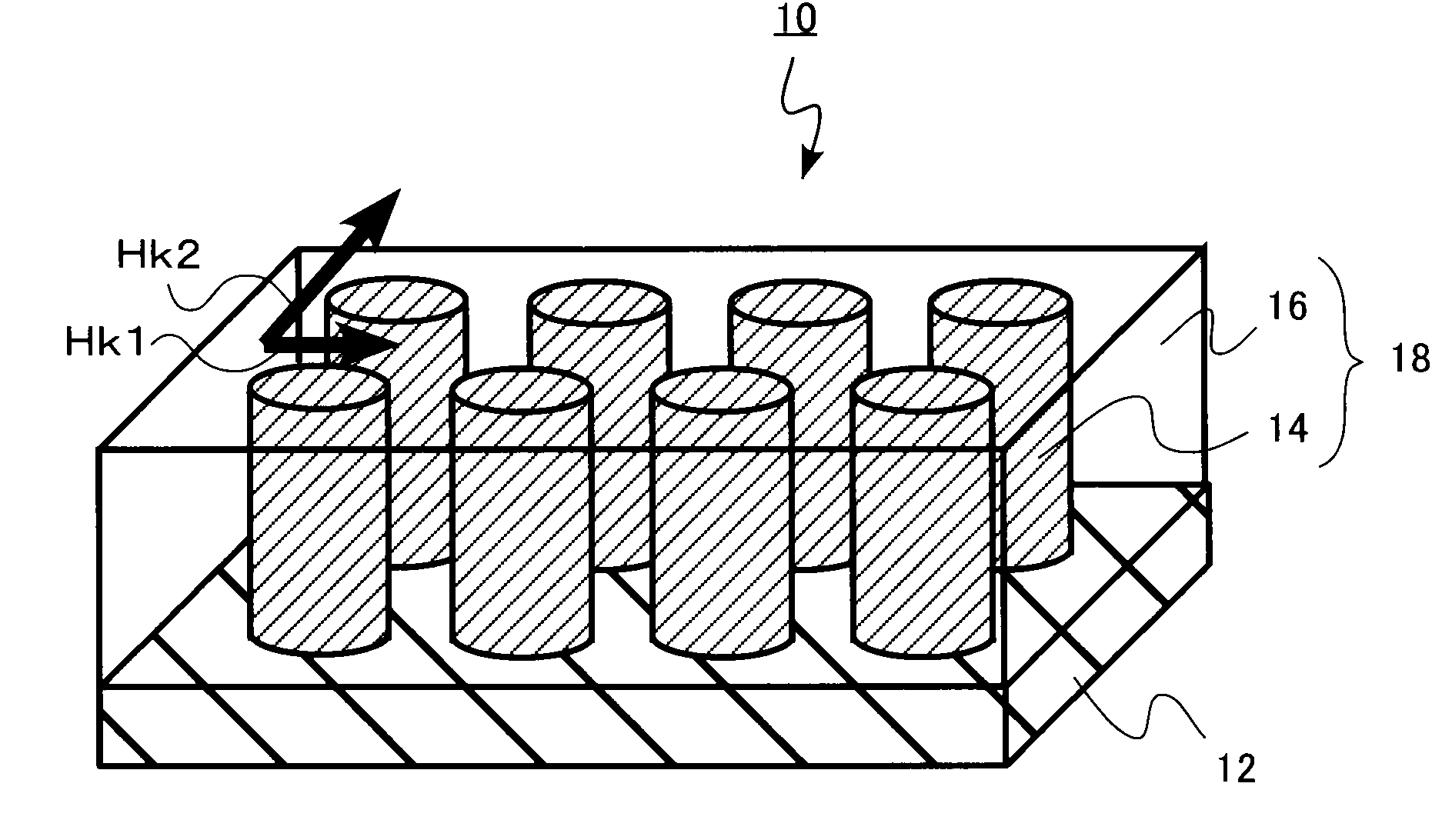
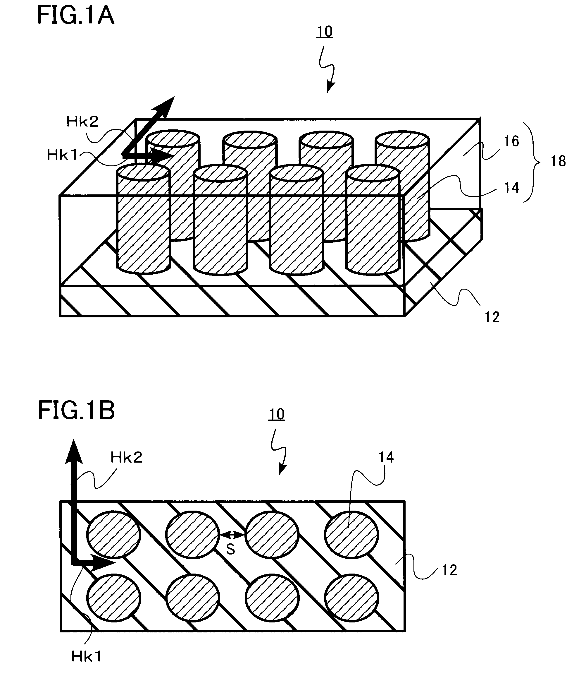
[0022]A high-frequency magnetic material in the first embodiment of the present invention includes a substrate and a composite magnetic film formed on the substrate and made of a magnetic phase forming a plurality of columnar bodies whose longitudinal direction is directed in a direction perpendicular to a surface of the substrate and an insulator phase filling gaps of the columnar bodies. In addition, the magnetic phase contains Fe and B. And the magnetic phase also contains at least one of Nb, Zr and Hf. And the magnetic phase is amorphous, and has in-plane uniaxial anisotropy of Hk2 / Hk1≧3 and Hk2≧3.98×10³ A / m when a minimal anisotropic magnetic field in a plane parallel to the surface of the substrate is Hk1 and a maximal anisotropic magnetic field is Hk2.

[0023]FIG. 1 is a diagram showing the structure of a high-frequency magnetic material in the present embodiment. FIG. 1A is a perspective view and FIG. 1B is a top view.

[0024]A high-frequency magnetic material 10 illustrated in ...

second embodiment

[0060]A high-frequency magnetic material according to the second embodiment of the present invention is the same as that according to the first embodiment except that the composite magnetic film further includes an insulator layer parallel to a substrate. Therefore, a description of portions that overlap with those of the first embodiment is omitted below.

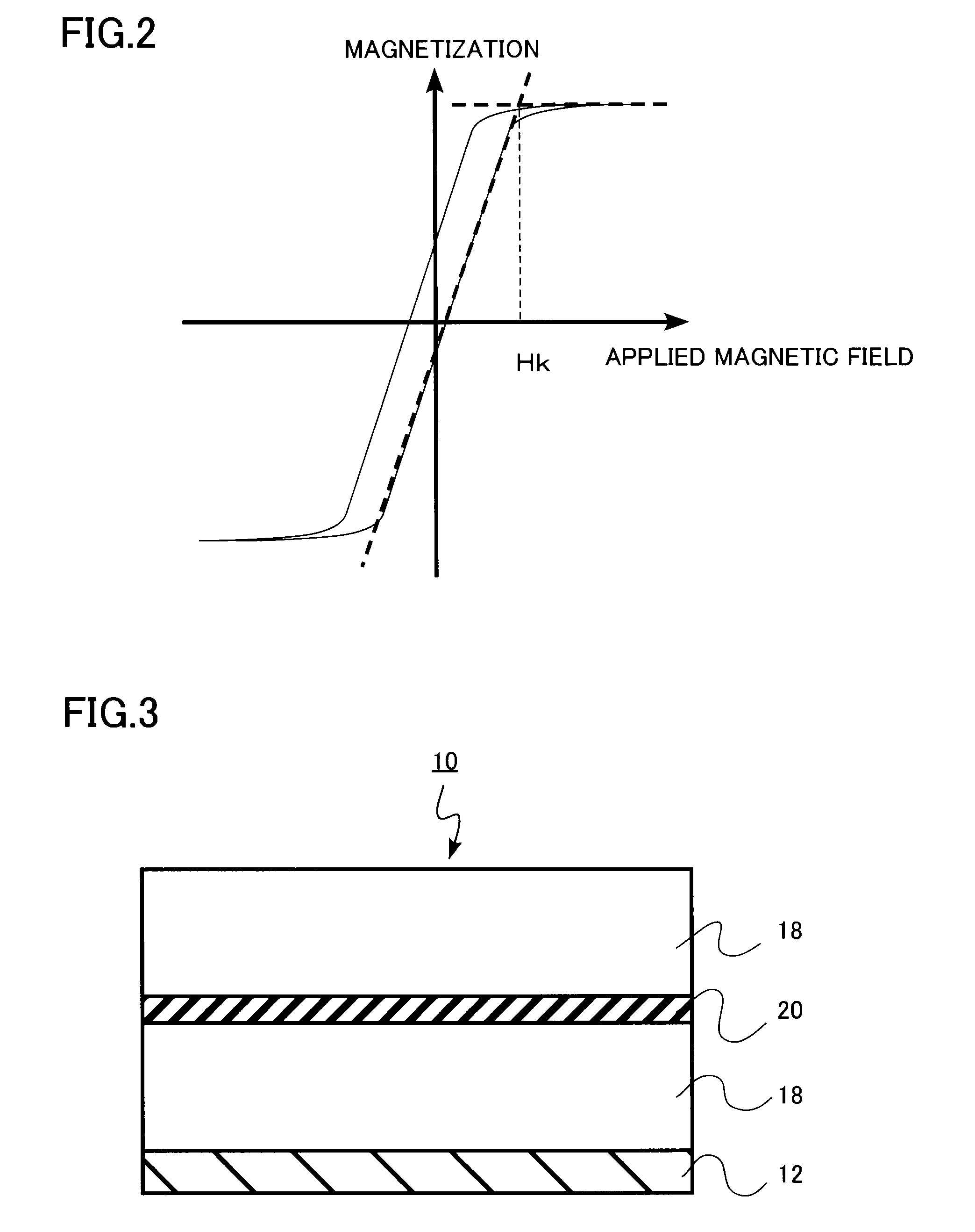
[0061]FIG. 3 is a sectional view of a high-frequency magnetic material in the present embodiment. As shown in FIG. 3, the high-frequency magnetic material in the present embodiment has a structure in which at least two layers of the composite magnetic film 18 are laminated on the substrate 12 and an insulator layer 20 is formed between these composite magnetic films 18.

[0062]By causing the insulator layer 20 to lie between two or more layers of the composite magnetic film 18, that is, by making the film thicker by separating the composite magnetic film 18 in the thickness direction through the insulator layer 20, it becomes possibl...

third embodiment

[0065]An antenna system according to the third embodiment of the present invention includes a feed terminal, an antenna element whose one end is connected to the feed terminal, and a high-frequency magnetic material for suppressing transmission losses of electromagnetic waves radiated from the antenna element. Then, the high-frequency magnetic material is the high-frequency magnetic material described in the first embodiment or the second embodiment. Therefore, a description of the high-frequency magnetic material is omitted below due to an overlap with that of the high-frequency magnetic material in the first embodiment or second embodiment.

[0066]FIG. 4 is a perspective view of an antenna system according to the present embodiment and FIG. 5 is a sectional view thereof. The high-frequency magnetic material 10 is provided between antenna elements 24 whose one end is connected to a feed terminal 22 and a wired substrate 26. The wired substrate 26 is, for example, a wired substrate of...


PUM

PropertyMeasurementUnit
Fractionaaaaaaaaaa
Thicknessaaaaaaaaaa
Thicknessaaaaaaaaaa

Abstract

A superior high-frequency magnetic material having a smaller ratio (μ″ / μ′) of a real part μ′ of permeability and an imaginary part μ″ of permeability in a high-frequency region and an antenna system using thereof are provided. The high-frequency magnetic material includes a substrate and a composite magnetic film formed on the substrate and made of a magnetic phase forming a plurality of columnar bodies whose longitudinal direction is directed in a direction perpendicular to a surface of the substrate and an insulator phase filling gaps of the columnar bodies. The magnetic phase contains at least one of Nb, Zr, and Hf, and Fe and B, is amorphous, and has in-plane uniaxial anisotropy of Hk2 / Hk1≧3 and Hk2≧3.98×10³ A / m when a minimal anisotropic magnetic field in a plane parallel to the surface of the substrate is Hk1 and a maximal anisotropic magnetic field is Hk2.

Description

CROSS-REFERENCE TO RELATED APPLICATION[0001]This application is based upon and claims the benefit of priority from Japanese Patent Application No. 2007-243899, filed on Sep. 20, 2007, the entire contents of which are incorporated herein by reference.FIELD OF THE INVENTION[0002]The present invention relates to a high-frequency magnetic material and an antenna system using thereof.BACKGROUND OF THE INVENTION[0003]High frequencies such as a GHz band are used as a frequency band of radio waves used by current mobile devices. However, for example, if a metal is present near an antenna of a mobile device when the antenna radiates electromagnetic waves, radiation of electromagnetic waves is disturbed due to an induced current generated in the metal. Thus, by arranging a high-frequency magnetic material (a material that exhibits high permeability in a high-frequency region) near the antenna to suppress generation of an unnecessary induced current, stability in radio frequency communication ...

Claims


Application Information

Patent Timeline
IPC IPC(8): H01Q1/00B32B7/00
CPCH01Q1/38Y10T428/24174Y10T428/325
Inventor EGUCHI, TOMOKOYONETSU, MAKINAKAGAWA, NAOYUKISUENAGA, SEIICHI
Owner KK TOSHIBA
Why Eureka
Try Eureka