Optical fiber cable and cable core production method

a production method and optical fiber technology, applied in the field of optical fiber cables, can solve the problems of deteriorating the manufacturability of the core part, increasing the transmission loss, and exposing the core part inside, and achieves the effects of suppressing the transmission loss of optical fibers, excellent workability, and never tightening excessively

Active Publication Date: 2021-10-21
FURUKAWA ELECTRIC CO LTD
View PDF0 Cites 0 Cited by
  • Summary
  • Abstract
  • Description
  • Claims
  • Application Information

AI Technical Summary

Benefits of technology

[0014]According to the first aspect of the invention, the cable core that is longitudinally wound by the wrapping tape is collectively twisted with the core part inside, and thus the wrap part of the wrapping tape is disposed helically to the longitudinal direction. This can prevent opening of the wrap part. At this time, the wrapping tape is wound longitudinally, not helically, and thus the wrapping tape never excessively tightens the optical fibers inside when being wound around.
[0024]The present invention can provide an optical fiber cable and a method for producing the optical fiber cable that can suppress transmission loss of optical fibers while maintaining excellent workability when taking out the optical fibers.

Problems solved by technology

This is because the wrapping tape is wound directly around the outer circumference of the optical fibers, and, if the wrapping tape is wound helically, tension of the wrapping tape presses the optical fibers, which may cause an increase in transmission loss and the like.
However, parts of the wrap part that are not pressed by the linear body may easily open up because of restoring force of the wrapping tape, causing the core part inside to be exposed.
However, reducing a winding pitch of the linear body to solve this issue requires lowering a linear speed at the time of production, which deteriorates its manufacturability.
Also, although increasing a wrapping margin of the wrap part may prevent the core part from being exposed, a lifted part of the wrap part, if there is any, may be caught by a chip that is passed through when placing the outer jacket.
Also, making the wrap part larger increases an amount of material used for the wrapping tape, causing an increase in cost, and, furthermore, this makes it harder to take out the optical fibers inside.

Method used


Image

  • Optical fiber cable and cable core production method
  • Optical fiber cable and cable core production method
  • Optical fiber cable and cable core production method

Examples


working examples

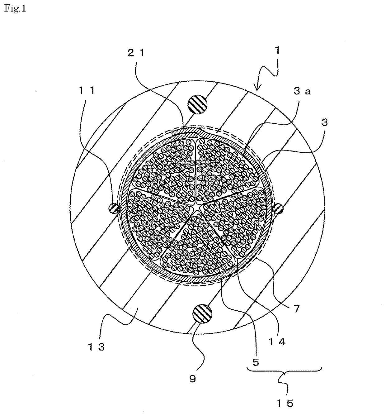
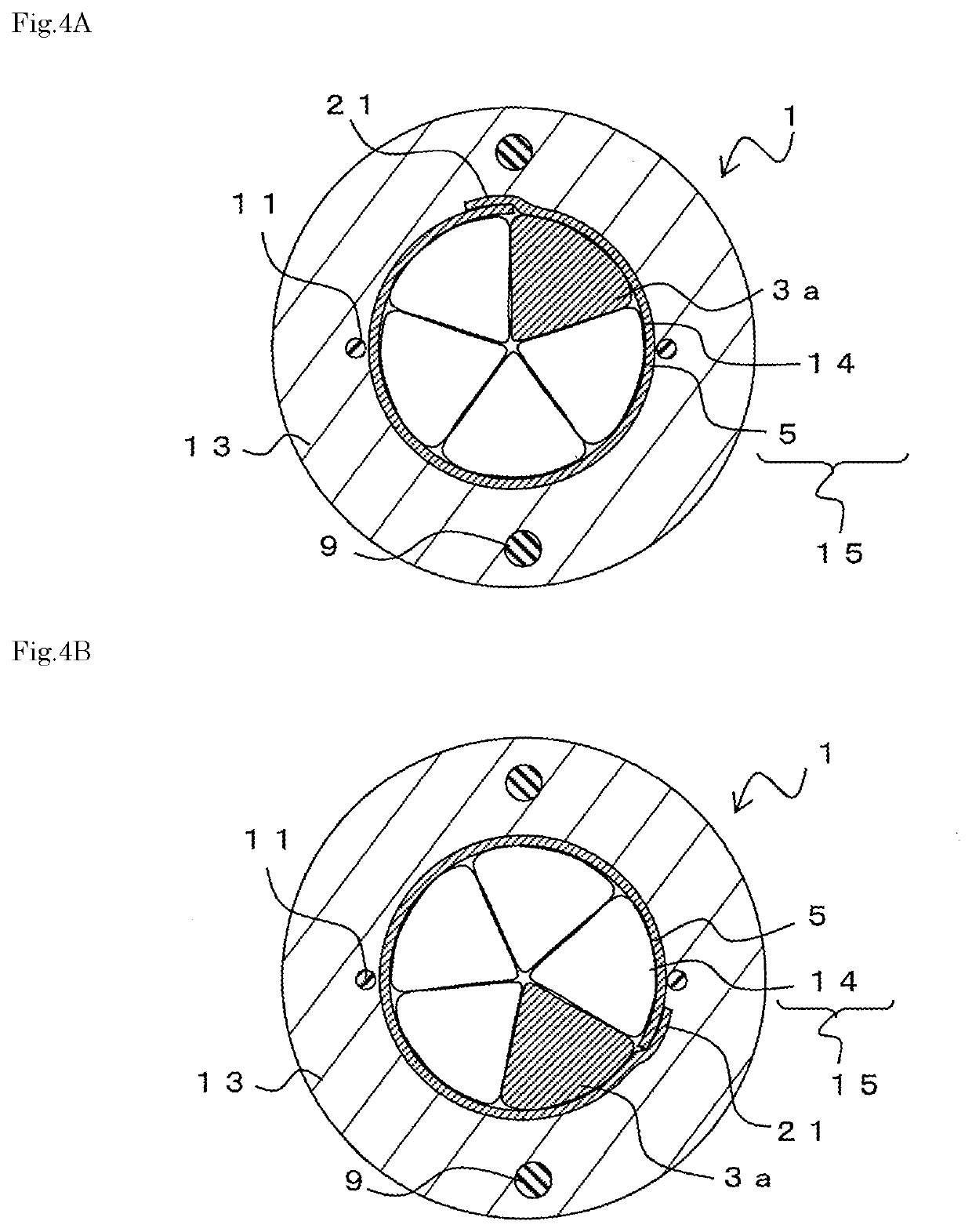
[0062]Transmission loss and opening (exposure of the core part 14) are evaluated with the various twisting pitch of the cable core 15. The optical fiber cable shown in FIG. 1 is used for the evaluation.

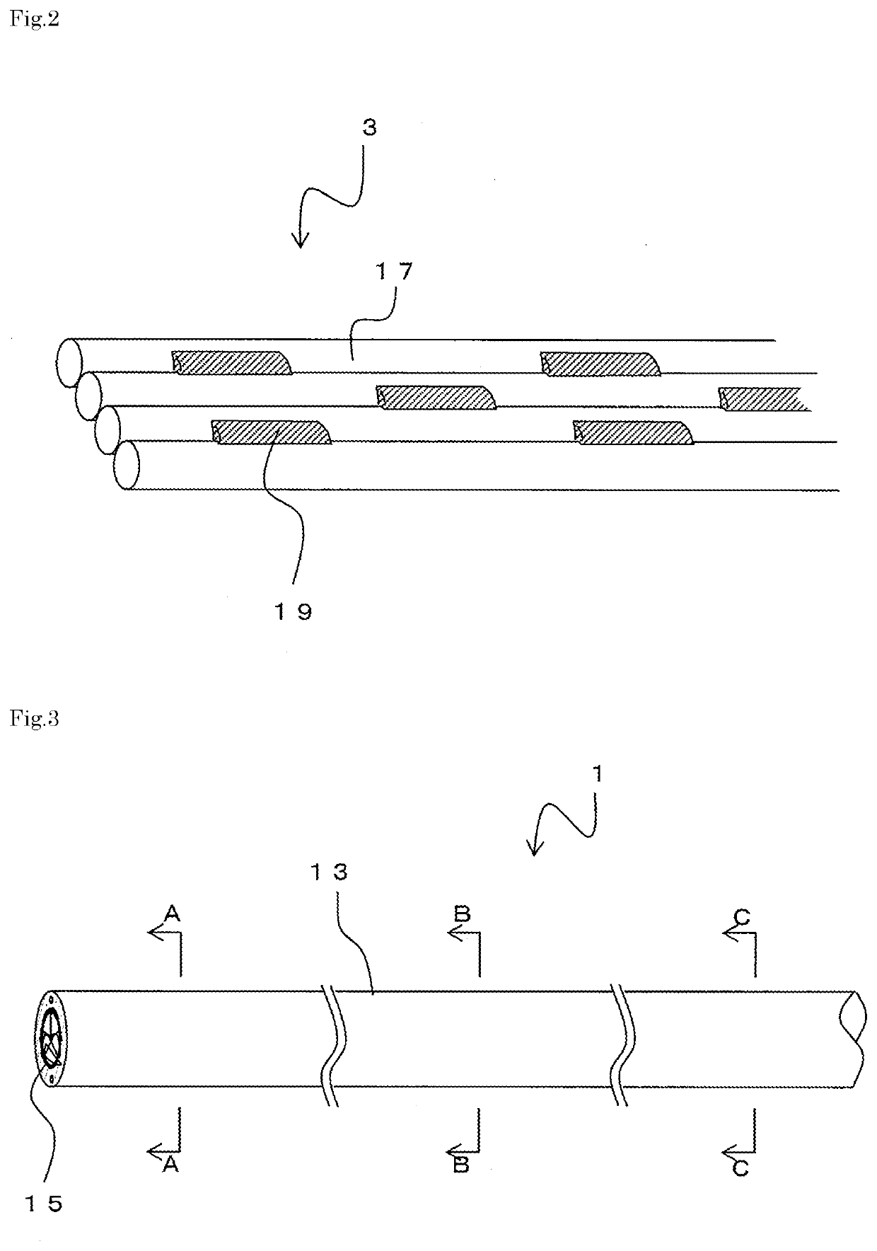
[0063]Eight optical fibers each having a diameter of 250 μm are bonded with each other intermittently to form an eight-core intermittently bonded optical fiber ribbon. Then, ten of the eight-core intermittently bonded optical fiber ribbons are twisted together and a plastic tape having a 2 mm width is wound thereon to form an 80-core optical fiber unit. Five of the 80-core optical fiber units are supplied and assembled together to form a core part, a wrapping tape made of a water-absorbent non-woven cloth is supplied and rolled up by a forming tool to be wound longitudinally around the outer circumference of the core part, and a binding string made of nylon is further wound around to form a 400-core cable core. A width of the wrap part of the wrapping tape is 5 mm.

[0064]The cable core...


PUM

PropertyMeasurementUnit
diameteraaaaaaaaaa
widthaaaaaaaaaa
widthaaaaaaaaaa

Abstract

A jacket is provided to the outer circumference of a cable core, a rip cord, and a tension member. The cable core, the rip cord, and the tension member are collectively covered by the jacket. A wrapping tape is longitudinally placed on the outer circumference of a core part so as to be wound therearound. Thus, immediately after the wrapping tape is longitudinally placed and wound, a wrap part thereof is formed so as to lie substantially straight in the axial direction of an optical fiber cable. In contrast, in an optical fiber cable, the cable core is obtained by combining and intertwining the core part and the wrapping tape. Because of this configuration, the wrap part of the wrapping tape is helically disposed in the longitudinal direction.

Description

TECHNICAL FIELD[0001]The present invention relates to an optical fiber cable accommodating a plurality of optical fibers, and to a method for producing a cable core of the optical fiber cable.BACKGROUND[0002]Due to a growing amount of information in recent years, there is a demand for an optical cable to accommodate more optical fibers with high density so that the amount of information transmitted per optical fiber cable can be increased. Accordingly, various types of optical fiber cables have been proposed.[0003]As such the optical fiber cable, a central core optical fiber cable including an outer jacket provided on an outer circumference of a plurality of optical fiber units with tension members buried in the outer jacket has been proposed (Japanese Unexamined Patent Application Publication No. 2016-206350 (JP-A-2016-206350), for example).[0004]Since a central core optical fiber cable uses no hard slotted rod, to protect optical fibers inside, a wrapping tape is wound around an o...

Claims


Application Information

Patent Timeline
Patent Type & Authority Applications(United States)
IPC IPC(8): G02B6/44
CPCG02B6/4434G02B6/4403G02B6/449G02B6/443G02B6/4413
Inventor YASUTOMI, TETSUYA
Owner FURUKAWA ELECTRIC CO LTD
Why Eureka
Try Eureka