Routing structure of two-core parallel shielded electric wire

a shielded electric wire and routing structure technology, applied in the direction of insulated conductors, waveguides, cables, etc., can solve the problems of increased transmission loss, increased strain applied to the two electric wires due to bending in a long axis direction, and sudden increase in attenuation amount, so as to suppress the effect of transmission loss reduction, transmission characteristics may be greatly reduced, and transmission loss reduction

Active Publication Date: 2020-01-16
YAZAKI CORP
View PDF0 Cites 0 Cited by
  • Summary
  • Abstract
  • Description
  • Claims
  • Application Information

AI Technical Summary

Benefits of technology

[0013]According to the routing structure of the two-core parallel shielded electric wire in the above aspect, the route is changed by bent twisting the two-core parallel shielded electrical wire in the short axis direction at the route change point along the long axis direction of the two-core parallel shielded electric wire, so that a decrease in transmission loss can be suppressed without bending the two-core parallel shielded electric wire in the long axis direction. Further, the number of bent twisted points in the short axis direction is 1.43 or less per meter in the two-core parallel shielded electric wire. Here, when the number of twisted points per unit length increases, the transmission loss may be 10% or more, and transmission characteristics may be greatly decreased. However, when the number is 1.43 or less per meter, the decrease in transmission loss can be suppressed to less than 10%. Therefore, the routing structure of the two-core parallel shielded electric wire can be provided in which the transmission loss due to bending is suppressed.

Problems solved by technology

In such a two-core parallel shielded electric wire, a metal foil tape or the like is used for the shield layer, but when the metal foil tape or the like is spirally wound on the two electric wires, a sack-out that is a sudden increase in an attenuation amount (a sharp drop in transmission characteristics) occurs.
That is, in the two-core parallel shielded electric wire, although the transmission loss due to bending in a short axis direction is small, a difference in strain applied to the two electric wires due to bending in a long axis direction increases, and the transmission loss increases.
However, in an actual routing environment (for example, routing in an automobile), bending in a space-saving manner is required, so that bending in the long axis direction is also required, resulting in increase in the transmission loss.

Method used


Image

  • Routing structure of two-core parallel shielded electric wire
  • Routing structure of two-core parallel shielded electric wire
  • Routing structure of two-core parallel shielded electric wire

Examples


Embodiment Construction

[0022]Hereinafter, the invention will be described according to a preferred embodiment. The invention is not limited to the embodiment described below, and can be appropriately modified without departing from the scope of the invention. In the embodiment described below, some configurations are not shown or described, but it goes without saying that a known or well-known technique is applied as appropriate to details of an omitted technique within a range in which no contradiction occurs to contents described below.

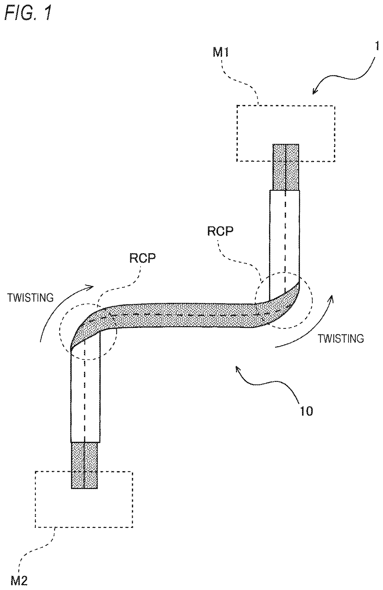
[0023]FIG. 1 is a top view showing a routing structure of a two-core parallel shielded electric wire according to an embodiment of the invention. As shown in FIG. 1, a routing structure 1 of a two-core parallel shielded electric wire 10 is a structure for routing the two-core parallel shielded electric wire 10 in a space-saving manner such as in a vehicle, which includes a first machine M1, a second machine M2 and the two-core parallel shielded electric wire 10.

[0024]The ...


PUM


Abstract

A routing structure of a two-core parallel shielded electric wire includes:
    • two insulated electric wires that are arranged in parallel; and
    • a shield layer that is attached around the two insulated electric wires and extends in a longitudinal direction of the two insulated electric wires.
In the routing structure, the two-core parallel shielded electric wire is rerouted by bent twisting the two-core parallel shielded electric wire in a short axis direction at a route change point along a long axis direction of the two-core parallel shielded electric wire, and the number of bent twisted points in the short axis direction is 1.43 or less per meter.

Description

CROSS-REFERENCE TO RELATED APPLICATIONS[0001]This application is based on Japanese Patent Applications No. 2018-132466 filed on Jul. 12, 2018, the entire contents of which are incorporated herein by reference.BACKGROUND1. Technical Field[0002]The present invention relates to a routing structure of a two-core parallel shielded electric wire.2. Background Art[0003]In related art, a two-core parallel shielded electric wire is proposed in which, for example, two electric wires are arranged in parallel and a shield layer is provided around the two electric wires (for example, see JP-A-2012-133991 and JP-A-2015-185527). The two-core parallel shielded electric wire is known to be suitable for transmitting a signal in a high frequency range of 200 Mbps or more, as compared to a two-core twisted shielded electric wire in which two electric wires are spirally wound with each other.[0004]In such a two-core parallel shielded electric wire, a metal foil tape or the like is used for the shield la...

Claims


Application Information

Patent Timeline
Patent Type & Authority Applications(United States)
IPC IPC(8): H01P3/02H01P1/00
CPCH01P3/02B60R16/023H01P1/00B60R16/0215H01B7/04H01B11/002H01B11/203H01B11/1852H01B7/0045
Inventor SHIMIZU, TOSHIHARUKONDO, HIROKI
Owner YAZAKI CORP
Why Eureka
Try Eureka