
Jointly-controlled wheel stopping anti-skid device and anti-skid method thereof

A joint control and anti-slip technology, which is applied in transportation and packaging, railway car body parts, railway signal and safety, etc., can solve problems such as unresolved leaks, hidden dangers of railway transportation safety, and accidents, so as to prevent slipping and Effects of shoe pulling accidents

Active Publication Date: 2012-09-12
吕贵刚
View PDF6 Cites 3 Cited by
  • Summary
  • Abstract
  • Description
  • Claims
  • Application Information

AI Technical Summary

Problems solved by technology

However, because the iron shoes currently used are relatively simple and lack relevant functions, they cannot meet the actual needs of production. Therefore, although the rules and regulations are perfect and the workers are also very dedicated, in actual work, due to negligence in preventing workers from slipping or lack of working conditions, resulting in leakage. Incidents of placing or forgetting to remove shoes, iron shoes being knocked off or stolen still happen from time to time, which may further cause accidents and bring great hidden dangers to the safety of railway transportation
In order to prevent accidents, the vast number of railway employees have also made some improvements to the iron shoes, for example: Chinese patents such as CN200420033611.8, but these patents mostly solve the problem of anti-theft or anti-collision, and do not solve the problems of missing, forgetting to remove shoes, etc.

Method used


Image

  • Jointly-controlled wheel stopping anti-skid device and anti-skid method thereof
  • Jointly-controlled wheel stopping anti-skid device and anti-skid method thereof
  • Jointly-controlled wheel stopping anti-skid device and anti-skid method thereof

Examples


Embodiment Construction

[0030] Below in conjunction with accompanying drawing, the present invention will be further described:

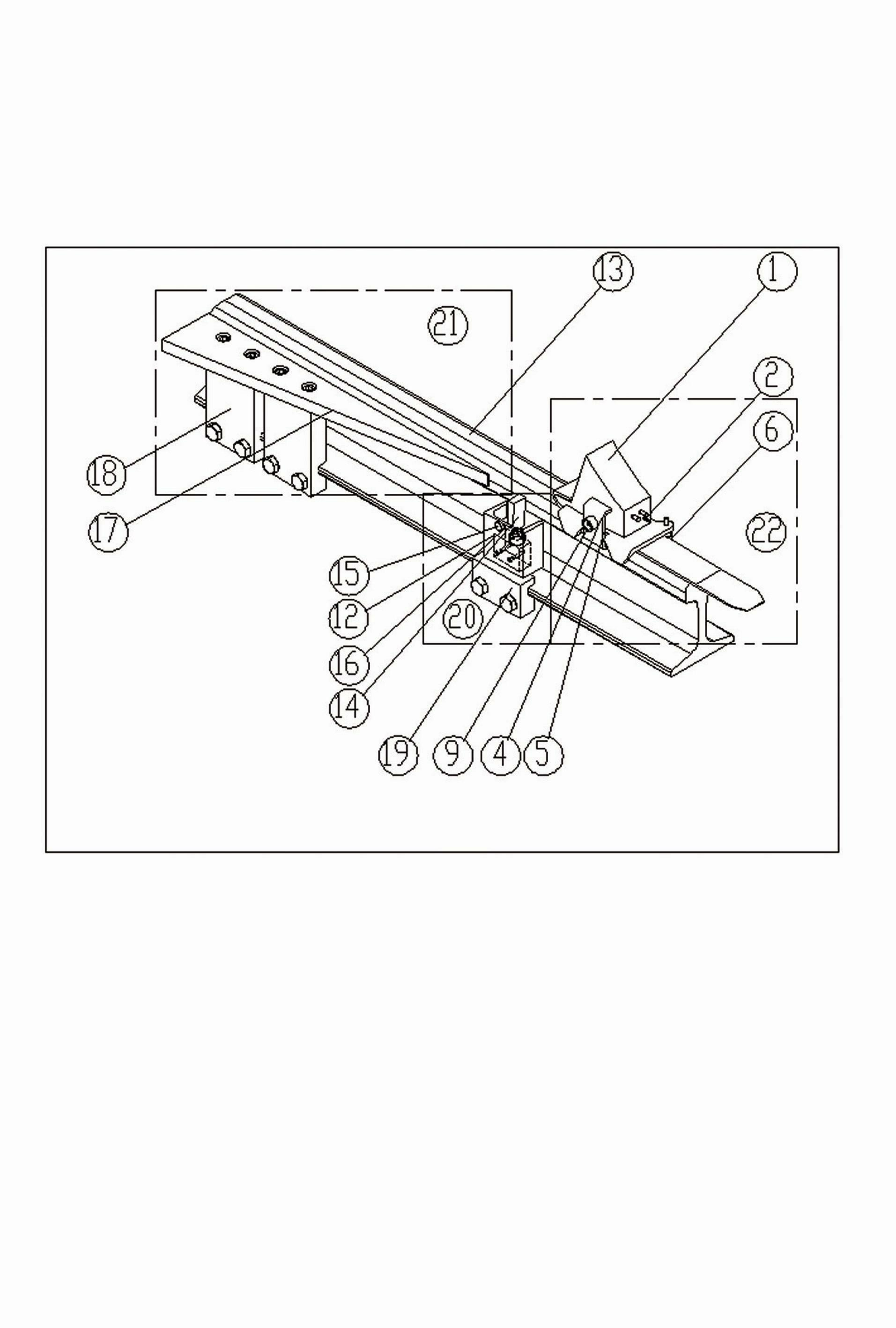
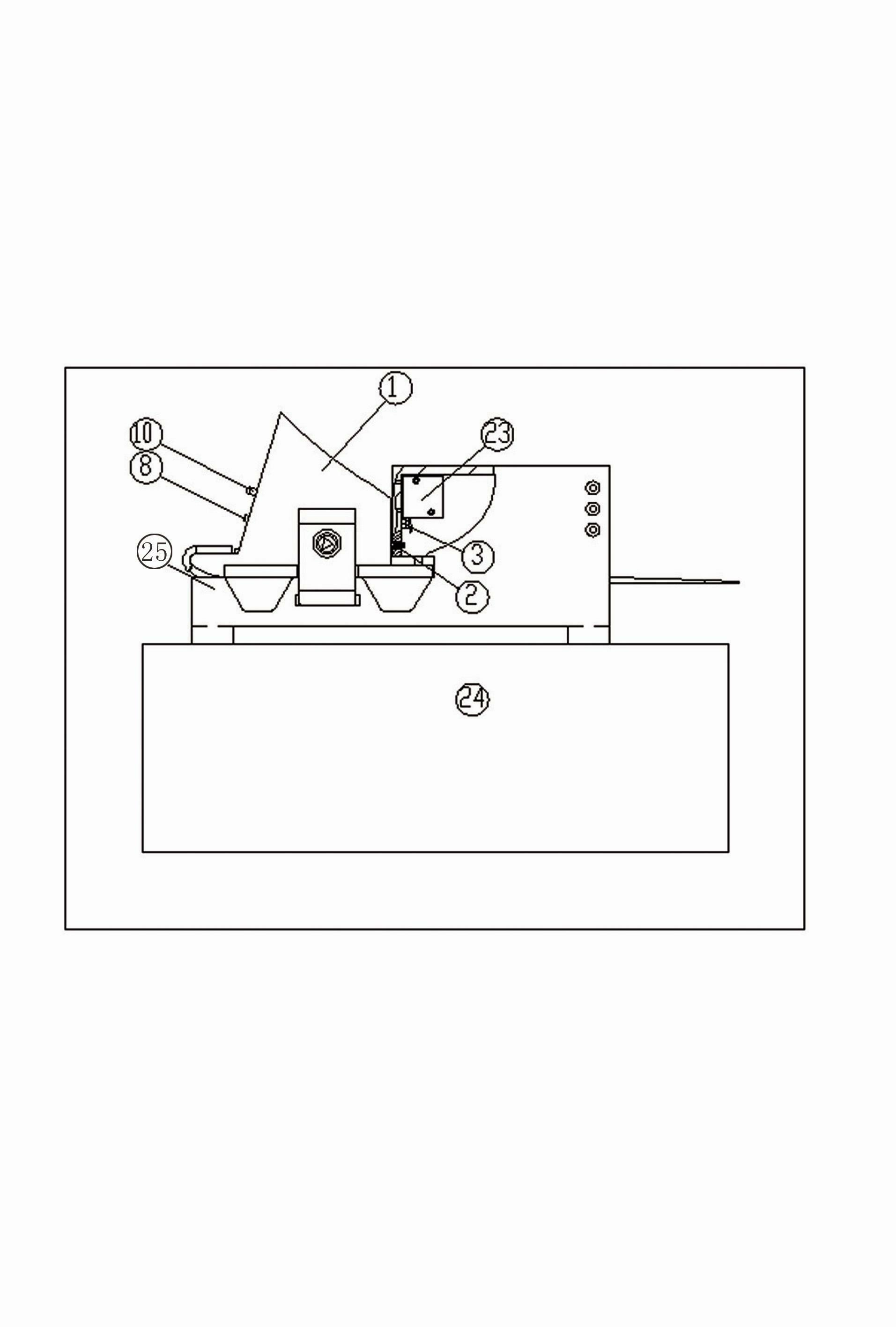
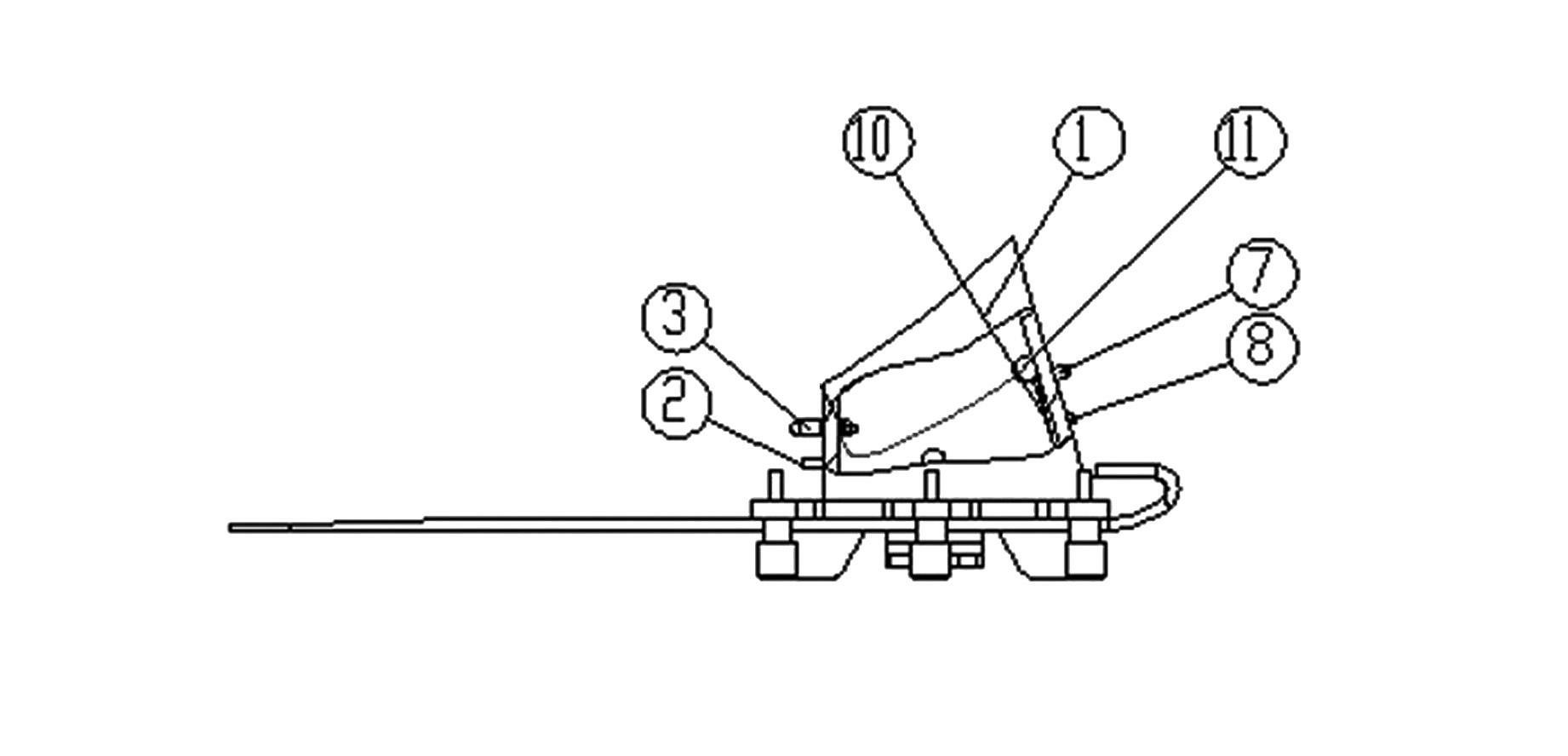
[0031] The invention provides a joint control wheel anti-slip device and its anti-slip method, such as figure 1 , figure 2 , image 3 with Figure 4 As shown in , the anti-slip device is composed of the following parts: multi-functional iron shoes 22, car-slip alarm switch 20, shoe-off device 21, joint control pendulum 24, and is characterized in that: car-slip alarm switch 20, shoe-off device 21 are all installed on the outside of the rail 13, and the joint control pendulum frame 24 is arranged beside the stock road that needs anti-slip; Car alarm switch 20 and shoe-removing device 21;

[0032] The multifunctional iron shoe 22 includes: multifunctional iron shoe body 1, identification pin 2, plug 3, locking stud 4, spring lock piece 5, column 6, light emitting diode 7, photosensitive element 8, retaining ring 9, control circuit board 10, rechargeable battery 11; mul...


PUM


Abstract

The invention belongs to the field of railway safety protection equipment and mainly relates to a jointly-controlled wheel stopping anti-skid device and an anti-skid method thereof. The jointly-controlled wheel stopping anti-skid device comprises a multifunctional iron shoe, a skid alarm switch, a shoe taking-off device and a jointly-controlled swing frame, wherein both the skid alarm switch and the shoe taking-off device are mounted on the outer side of a steel rail, and the jointly-controlled swing frame is arranged beside a station track needing skid prevention. When in the anti-skid state, the multifunctional iron shoe is mounted on the steel rail, and the skid alarm switch and the shoe taking-off device are respectively positioned in front of the multifunctional iron shoe. When not in the anti-skid state, the multifunctional iron shoe is mounted on the jointly-controlled swing frame. The jointly-controlled wheel stopping anti-skid device and the anti-skid method thereof have the advantages that theft, omitted placement, shedding can be prevented, shoe patrolling at night can be facilitated, the iron shoe can be taken off automatically when forgotten to be removed, shoe pulling accidents can be effectively prevented, and the jointly-controlled wheel stopping anti-skid device and the anti-skid method thereof are applicable to popularization and application.

Description

technical field [0001] The invention relates to an anti-slip device for railway wheels and an anti-slip method thereof, in particular to a joint control with departure signals, which can prevent theft, prevent leaking, prevent falling off, and facilitate night patrol; The utility model relates to a joint control anti-slip device and an anti-slip method thereof, which can take off the shoes by itself to prevent shoe pulling accidents, and belong to the field of railway safety protection equipment. Background technique [0002] Anti-slip device, also known as iron shoes. Using iron shoes to prevent slipping is one of the main measures for railway enterprises to prevent slipping. According to the "Railway Technical Management Regulations" of the Ministry of Railways of the People's Republic of China, vehicles should be parked at marshalling stations and section stations on lines other than arrival and departure lines and shunting lines; Securely fix iron shoes (wheel stoppers...

Claims


Application Information

Patent Timeline
Patent Type & Authority Applications(China)
IPC IPC(8): B61H7/02B61L23/00
Inventor 吕贵刚吕品
Owner 吕贵刚
Learn More