Connecting structure of clutch branch pump and release bearing

A technology of separation bearings and clutch cylinders, which is applied in the field of automobile transmission systems, can solve problems such as poor reliability and inconvenient operation, and achieve the effects of low cost, easy installation and maintenance, and improved safety and reliability

Inactive Publication Date: 2012-09-12
DONGFENG AUTOMOBILE COMPANY
View PDF6 Cites 2 Cited by
  • Summary
  • Abstract
  • Description
  • Claims
  • Application Information

AI Technical Summary

Problems solved by technology

This method brings problems such as inconvenient operation and poor reliability.

Method used


Image

  • Connecting structure of clutch branch pump and release bearing
  • Connecting structure of clutch branch pump and release bearing
  • Connecting structure of clutch branch pump and release bearing

Examples


Embodiment Construction

[0015] The present invention will be further explained below in conjunction with accompanying drawing and embodiment:

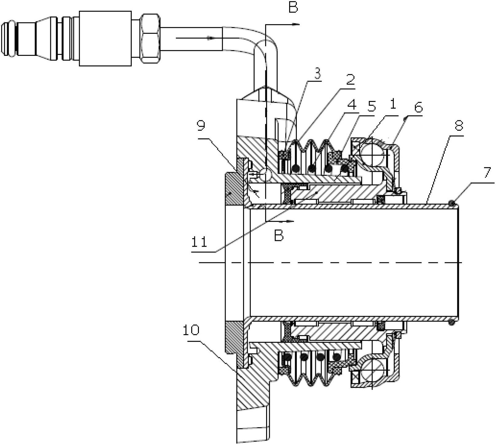
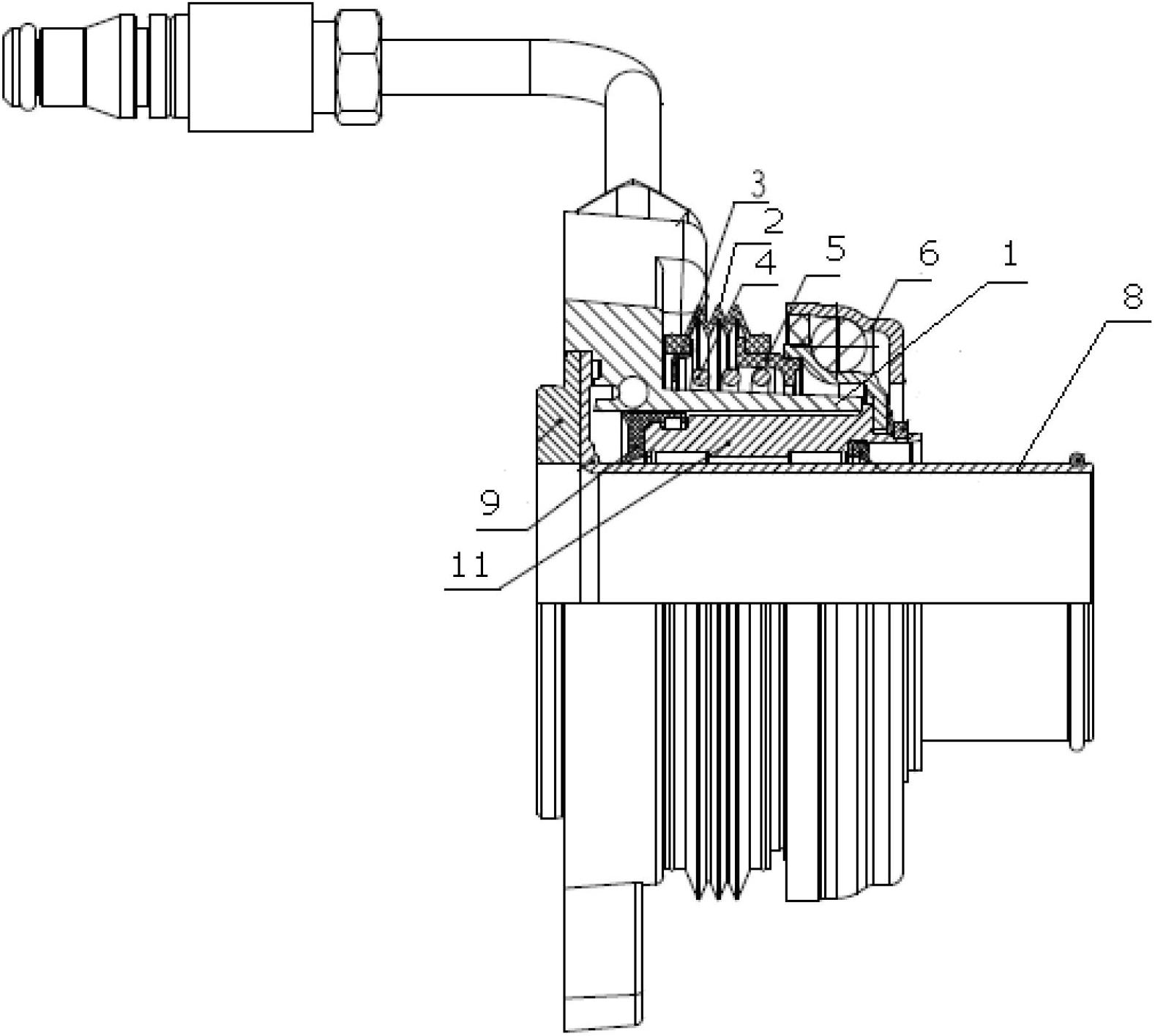
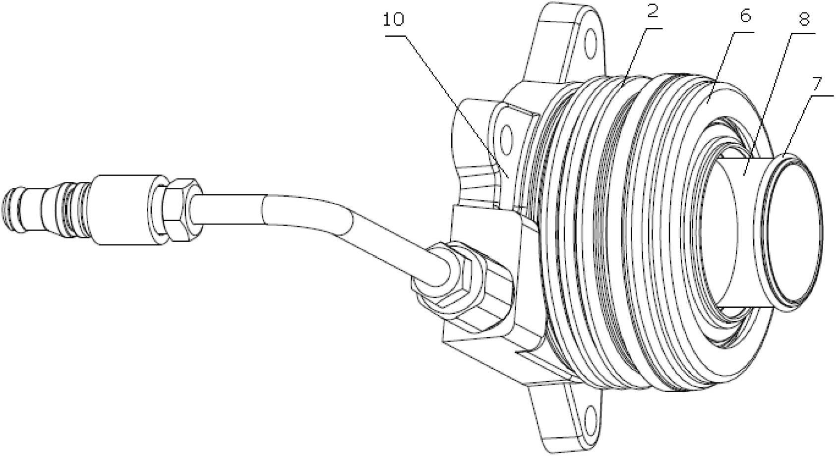
[0016] refer to figure 1 and image 3 A hydraulic piston pump 9 is provided between the inner cylinder 8 and the outer cylinder 1 of the clutch cylinder 10, and the outer cylinder 1 is also covered with a compression spring 4 enclosed in a dust cover 2. Both ends of the dust cover 2 are provided with a front fixing ring 5 which contacts (or connects) with the front end of the compression spring 4 and a rear fixing ring 3 which contacts (or connects) the rear end of the compression spring 4, and the dust cover 2 is deformable The material (such as rubber, etc.) can be deformed correspondingly with the compression deformation of the compression spring 4. The inner cylinder 8 of the clutch cylinder 10 is also covered with a release bearing assembly 6, and the rear end surface of the release bearing assembly 6 is in contact with the hydraulic pressure. The pist...


PUM


Abstract

The invention discloses a connecting structure of a clutch branch pump and a release bearing, solving the problems of inconvenience for operation and poor reliability caused by the condition that the conventional clutch branch pump and the release bearing are connected by a shifting fork. The technical scheme is as follows: the connecting structure comprises the clutch branch pump and a release bearing assembly, wherein the clutch branch pump comprises an inner cylinder body, an outer cylinder body and a hydraulic piston pump sleeved between the inner cylinder body and the outer cylinder body; the release bearing assembly is sleeved on the inner cylinder body; and the rear end of the release bearing assembly is connected with a piston of a hydraulic piston pump. The connecting structure of the clutch branch pump and the release bearing has the advantages of simplicity, high reliability, lower cost, small size and high transmission efficiency without regulating the clutch branch pump due to wearing of a clutch plate friction block of a clutch.

Description

technical field [0001] The invention relates to an automobile transmission system, in particular to a connection structure of a clutch cylinder and a release bearing Background technique [0002] The clutch operation in the automobile transmission system generally adopts the hydraulic piston pump that hydraulically pushes the clutch cylinder, and the force is transmitted between the cylinder and the release bearing assembly through a lever (fork), and the front end of the release bearing assembly acts on the release finger of the clutch. , The release bearing assembly is fixed on the transmission input shaft through the bearing seat. Since the clutch slave cylinder and the release bearing assembly are connected by a shift fork, the efficiency is low. As the friction plate of the clutch driven disc wears out, the release finger will move toward the transmission, and the release bearing assembly also needs to move toward the transmission. Therefore, it is necessary to frequen...

Claims


Application Information

Patent Timeline
Patent Type & Authority Applications(China)
IPC IPC(8): F16D25/12
Inventor 王波雷永超高永东龚洪陈传洁徐敏
Owner DONGFENG AUTOMOBILE COMPANY
Why Eureka
Try Eureka