Speed reducer for heavy-duty vehicle

A technology for heavy-duty vehicles and reducers, applied in transmission parts, gear transmissions, belts/chains/gears, etc., can solve the problems of inability to meet the requirements of large torque output, small deceleration, etc., and achieve compact structure and reduction ratio. The effect of large and large output torque

Active Publication Date: 2012-09-12
国营红山机械厂
View PDF6 Cites 0 Cited by
  • Summary
  • Abstract
  • Description
  • Claims
  • Application Information

AI Technical Summary

Problems solved by technology

The side reducer of the original crawler vehicle adopts the first-stage side reducer, and the deceleration achieved by it is relatively small, which cannot meet the requirements of the existing vehicles for bulldozing, lifting, digging and other operating functions such as large torque output.

Method used


Image

  • Speed reducer for heavy-duty vehicle
  • Speed reducer for heavy-duty vehicle

Examples


Embodiment Construction

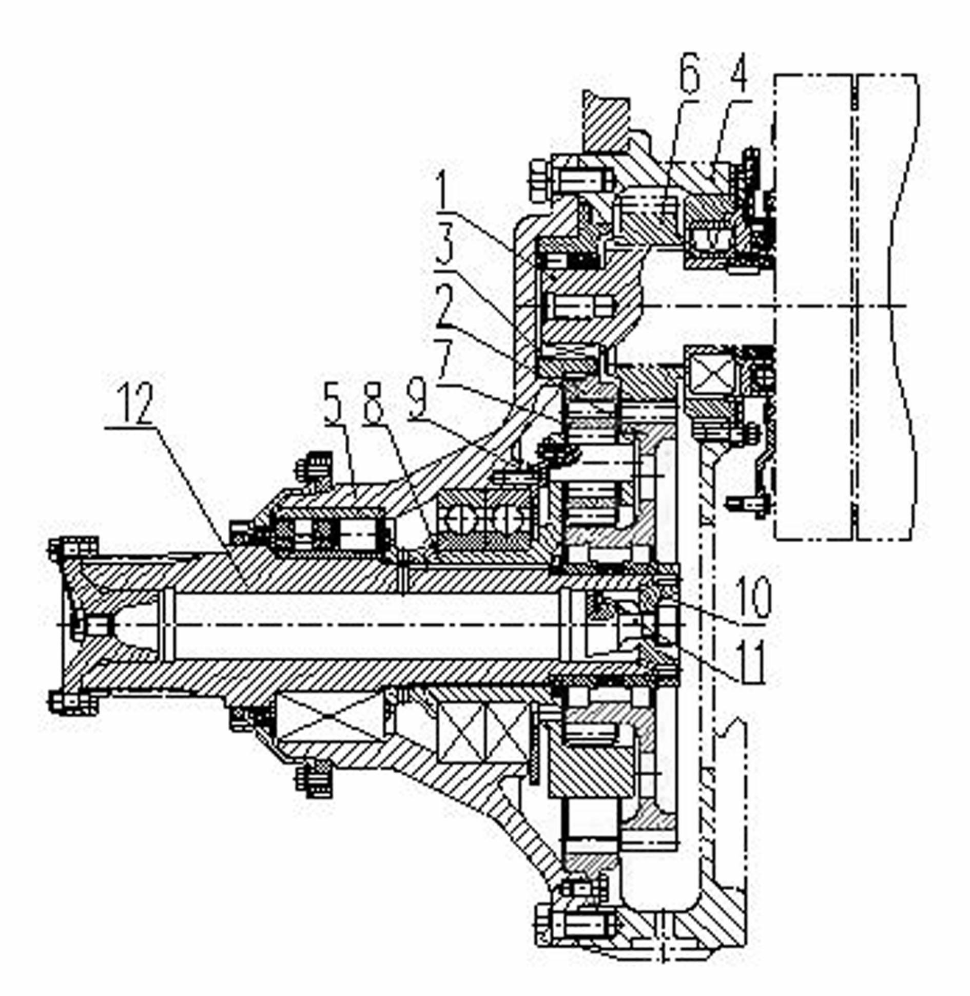
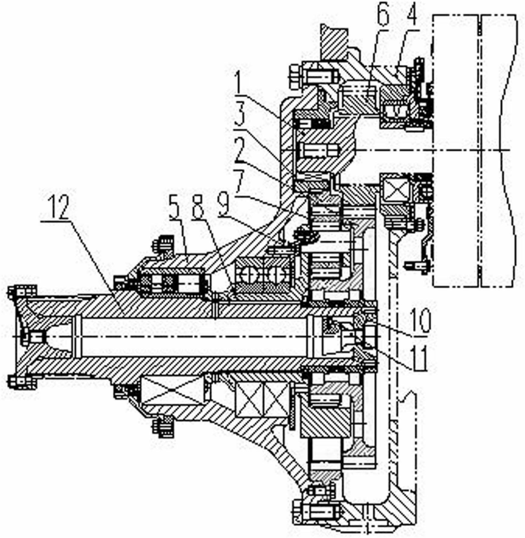
[0010] A reducer for heavy vehicles such as figure 1 As shown, it includes driving shaft 1, driven gear 2, ring gear 3, gear box 4, gear box cover 5, driving gear 6, planetary gear 7, planetary frame 8, planetary gear shaft 9, fixed screw plug 10, cone head Screw rod 11 and driven shaft 12, driving shaft 1 is provided with driving gear 6, one end of driving shaft 1 is arranged on gear box 4, the other end is arranged on gear box cover 5, driven shaft 12 is arranged on gear box cover 5, The driven gear 2 is set on the driven shaft 12 through the fixed screw plug 10 and the conical head screw 11, the planetary frame 8 is connected with the driven shaft 12, the planetary frame 8 is provided with a planetary gear shaft 9, and the planetary gear 7 is set on the planetary gear shaft 9 , the passive gear 2 meshes with the driving gear 6 and the planetary gear 7 respectively, the gear case cover 5 is arranged on the gearbox 4 , the ring gear 3 is arranged on the gear case cover 5 , a...


PUM


Abstract

The invention relates to a speed reducer for a heavy-duty vehicle. A driving shaft (1) is provided with a driving gear (6), one end of the driving shaft (1) is arranged on a gearbox (4), the other end of the driving shaft (1) is arranged on a gearbox cover (5), a driven shaft (12) is arranged on the gearbox cover (5), a driven gear (2) is arranged on the driven shaft (12) by a fixed plug screw (10) and a conehead screw rod (11), a planetary frame (8) is connected with the driven shaft (12) and provided with a planetary gear shaft (9), a planetary gear (7) is arranged on the planetary gear shaft, the driven gear (2) is meshed with the driving gear (6) and the planetary gear (7) respectively, the gearbox cover (5) is arranged on the gearbox (4), a gear ring (3) is arranged on the gearbox cover (5) and meshed with the planetary gear (7). By adopting the secondary speed reduction mechanism, the speed reducer has large speed reduction ratio, large output torque, and can meet the requirements of multiple operation functions such as bulldozing, hoisting, excavation and the like.

Description

[0001] technical field [0002] The invention relates to a transmission, in particular to a speed reducer for heavy vehicles. Background technique [0003] The function of the gearbox is mainly to reduce the output of the motor and increase the output of the motor. The speed of the engine or diesel engine is generally different from the speed we need, and the output speed is very high. In order to obtain the required speed or torque, the speed of the power source needs to be reduced. [0004] As the last stage reduction device in the drive train, the gearbox is used to further reduce the speed and increase the torque of the output shaft. The original tracked vehicle side reducer adopts the first-stage side reducer, which achieves a relatively small deceleration and cannot meet the requirements of the existing vehicles for bulldozing, lifting, digging and other operating functions such as large torque output. Contents of the invention [0005] The technical problem to...

Claims


Application Information

Patent Timeline
Patent Type & Authority Applications(China)
IPC IPC(8): F16H1/28F16H57/023F16H57/08F16H57/027
Inventor 杨建英张萍王晓兵张康民
Owner 国营红山机械厂
Why Eureka
Try Eureka