Backlight module and LCD (liquid crystal display)

A technology of liquid crystal display and backlight module, applied in the direction of instruments, optics, light guide, etc., can solve the problems affecting the coupling efficiency, the minimum coupling distance between the light source and the light guide plate cannot be guaranteed, etc., and achieve the effect of ensuring the coupling efficiency.

Inactive Publication Date: 2012-09-12
TCL CHINA STAR OPTOELECTRONICS TECH CO LTD
View PDF5 Cites 8 Cited by
  • Summary
  • Abstract
  • Description
  • Claims
  • Application Information

AI Technical Summary

Problems solved by technology

[0010] An object of the present invention is to provide a backlight module to solve the problem in the prior art when the light guide plate changes along the gravity direction because the gravity direction of the light guide plate is perpendicular to the light coupling distance direction in the single short side light incident mode. , leading to the technical problem that the minimum light coupling distance between the light source and the light guide plate cannot be guaranteed, which in turn affects the light coupling efficiency

Method used


Image

  • Backlight module and LCD (liquid crystal display)
  • Backlight module and LCD (liquid crystal display)
  • Backlight module and LCD (liquid crystal display)

Examples


Embodiment Construction

[0037] The following descriptions of the various embodiments refer to the accompanying drawings to illustrate specific embodiments in which the present invention can be practiced.

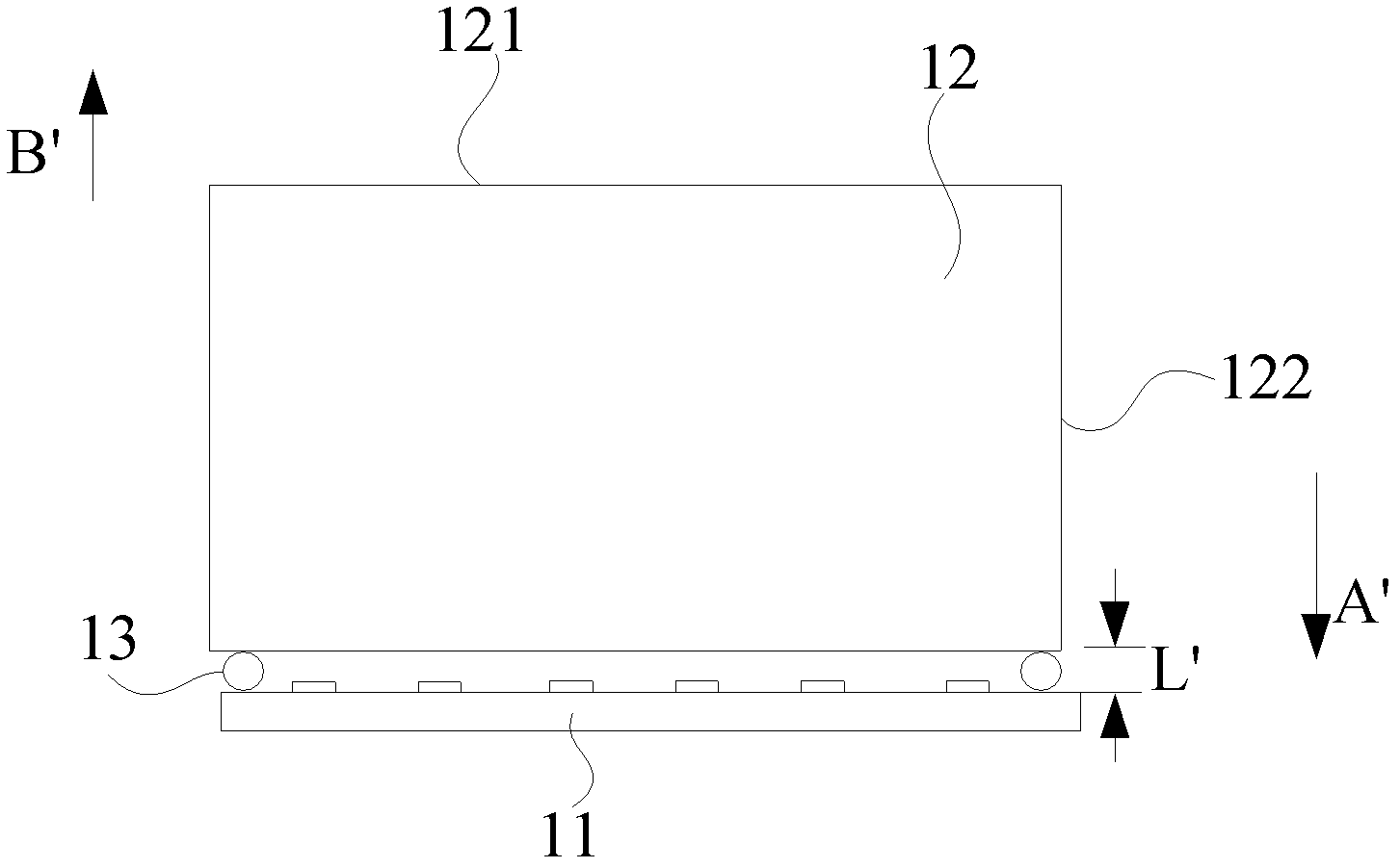
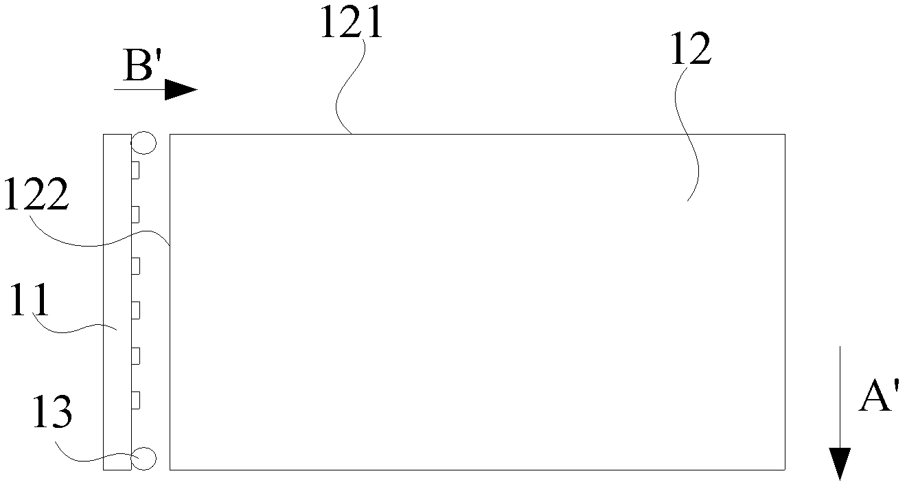
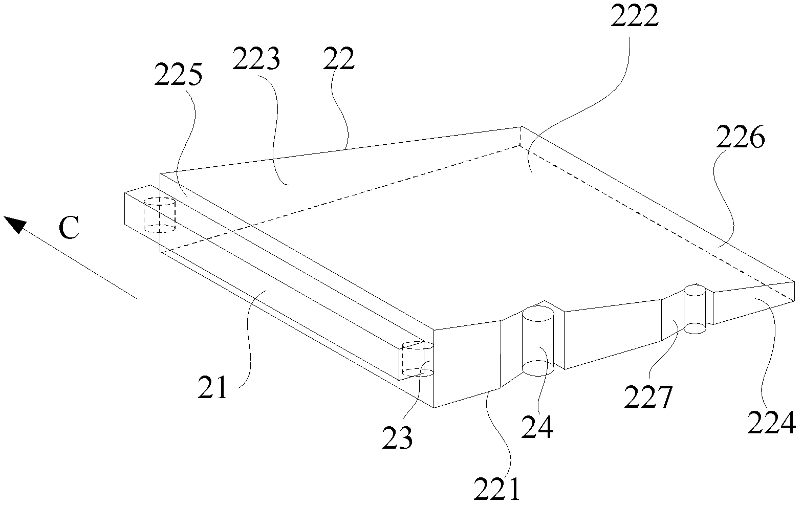
[0038] see image 3 , image 3 It is a structural schematic diagram of the first preferred embodiment of the backlight module in the present invention, Figure 4 for image 3 top view. The backlight module includes a light source 21 , a light guide plate 22 , a positioning column 23 and a supporting column 24 .

[0039] The light guide plate 22 includes a reflective surface 221 and a light-emitting surface 222, between which the reflective surface 221 and the light-emitting surface 222 include an upper bottom surface 223 and a supporting bottom surface 224, and also includes a left side 225 and a right side 226, wherein, The length of the upper bottom surface 223 or the supporting bottom surface 224 is greater than the length of the left side 225 or the right side 226 .

[0040] The support bo...


PUM


Abstract

The invention discloses a backlight module and an LCD (liquid crystal display). The backlight module comprises an LGP (light guide plate) and a light source, wherein the LGP comprises a reflecting surface and a light-emitting surface, two bottom surfaces and two side surfaces are arranged between the reflecting surface and the light-emitting surface, and each of the two bottom surfaces is provided with a supporting bottom surface; the light source is in long strip shape and is arranged corresponding to one of the side surfaces of the LGP, the backlight module further comprises supporting pillars, and the supporting bottom surface is provided with a contact inclined plane; the supporting pillars clings to the contact inclined plane; one gravity direction is parallel to the length direction of the light source, when the LGP changes along the gravity direction, a force is generated between the LGP and the supporting pillars, and the supporting pillars push the LGP to the light source under the effect of the force.

Description

【Technical field】 [0001] The invention relates to the technical field of liquid crystal display, in particular to a backlight module and a liquid crystal display. 【Background technique】 [0002] The single-side incident light mode in the backlight module is becoming more and more popular. Among them, the single-side light input mode only needs to set the light source on one side of the light guide plate, so the number of printed circuit boards, the number of light source (such as LED) heat sinks, the number of light sources, the number of light source driving boards, and components can be reduced. Quantity, number of channels, number of wires, and number of connectors, etc., and easy to assemble. [0003] see figure 1 , figure 1 It is a top-view structure schematic diagram of a backlight module with a single-side light incident mode in the prior art, and more specifically, the single-side light incident mode is a single long-side light incident mode. [0004] The backlig...

Claims


Application Information

Patent Timeline
Patent Type & Authority Applications(China)
IPC IPC(8): F21S8/00F21V17/00G02F1/13357
CPCG02B6/0088G02B6/0046G02B6/0091
Inventor 张光耀
Owner TCL CHINA STAR OPTOELECTRONICS TECH CO LTD
Why Eureka
Try Eureka