Light emitting diode light source structure

A technology of light-emitting diodes and light-emitting diodes, which is applied in the direction of electric solid-state devices, semiconductor devices, electrical components, etc., can solve problems such as unsafe hidden dangers, unsatisfactory, low light efficiency, etc., to achieve safety protection, product cost reduction, and light emission high efficiency effect

Inactive Publication Date: 2012-09-12
厦门宝晨照明科技有限公司
View PDF5 Cites 12 Cited by
  • Summary
  • Abstract
  • Description
  • Claims
  • Application Information

AI Technical Summary

Problems solved by technology

[0004] The above-mentioned conventional diode light sources all have the following disadvantages: the external electro-optical conversion efficiency of the light-emitting diode is 30-40%, the white light luminous efficiency is 120-170lm / W, and the light efficiency is low
However, the packaging structure of this light-emitting diode light source emits light from one side and has side-lighting dead angles, which cannot meet the needs of four-sided light-emitting lighting fixtures without dead angles, and the phosphors and light-emitting diodes are not completely sealed in the substrate, which is unsafe. Hidden danger

Method used


Image

  • Light emitting diode light source structure
  • Light emitting diode light source structure
  • Light emitting diode light source structure

Examples


Embodiment 1

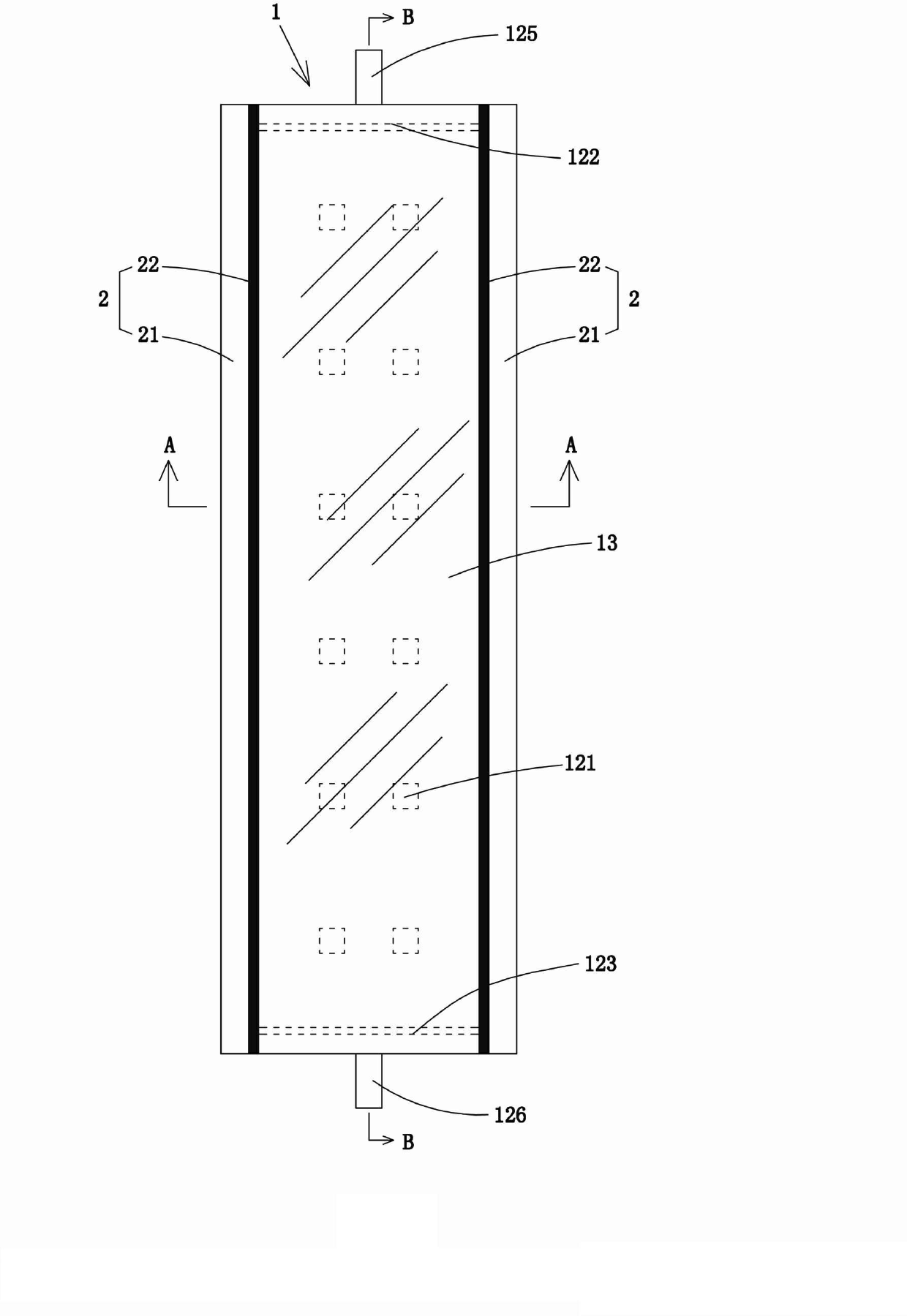
[0029] refer to Figure 2 to Figure 4 . A light-emitting diode light source structure, including a cuboid package body 1 composed of a light-transmitting substrate 11, a light-emitting diode device, and a light-transmitting top plate 13, and the light-emitting diode device is fixed and packaged on the opposite surface of the light-transmitting substrate 11 and the light-transmitting top plate 13 Between; the package main body 1 is a strip-shaped structure, and the light-transmitting side panels 2 are fixedly attached to the sides of the two lengthwise directions.

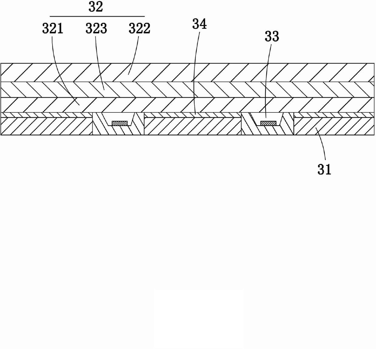
[0030] refer to Figure 2 to Figure 4 . The light-transmitting substrate 11 and the light-transmitting top plate 13 are rectangular transparent sheets of equal specifications. The light-transmitting substrate 11 and the light-transmitting top plate 13 respectively include a first transparent sheet 101 and a second transparent sheet 103 fixedly stacked together, and fluorescent glue is evenly coated between the op...

Embodiment 2

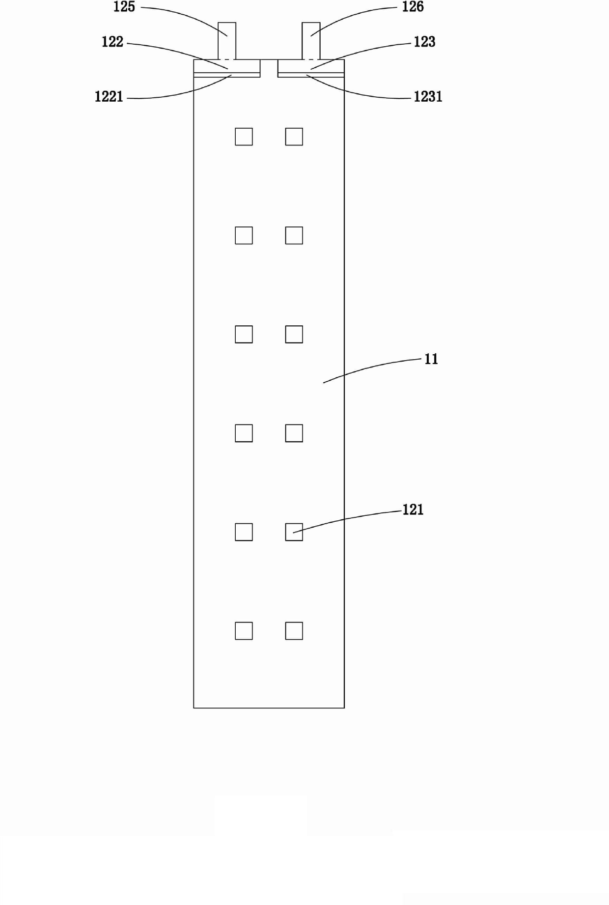
[0040] The difference between this embodiment and the first embodiment above is that: refer to Figure 6 and Figure 7 . Positive and negative light-emitting electrode sheets 122, 123 are spaced at the side edges of the same width side of the light-transmitting substrate 11, and the positive and negative connection electrodes 125, 126 protrude from the width side of the package body 1; preferably, the positive and negative light emitting The electrode sheets 122 and 123 are fixed and glued to the light-transmitting substrate 11 and the light-transmitting top plate 13 by insulating glue. The other width side of the package body 1 is also fixedly attached with a transparent side plate 2'. The two longitudinal sides of the package body 1 are packaged with light-transmitting side panels 2 , and the other width side of the package body 1 is also packaged with a light-transmitting side panel 2 ′. The light side plate 2 is similar, and it includes a transparent sheet 21' and a fluor...


PUM


Abstract

The invention discloses a light emitting diode light source structure, which comprises a packaging main body, wherein the packaging main body is composed of a light transmitting substrate, a light emitting diode device fixed on the upper surface of the light transmitting substrate and a light transmitting top plate correspondingly packaged on the light emitting diode device; the light emitting diode device comprises an LED (Light Emitting Diode) light emitting chip, a positive light emitting electrode slice and a negative light emitting electrode slice; the LED light emitting chip and the light emitting electrode slices are connected; a transparent silica gel layer for sealing the LED light emitting chip is injected between the light transmitting substrate and the light transmitting top plate; the side surface of at least one packaging main body is fixedly stuck with a light transmitting side plate; the light transmitting substrate and the light transmitting top plate respectively comprise a first transparent sheet and a second transparent sheet which are fixedly overlapped; a fluorescence rubber layer is evenly coated between the opposite surfaces of the first transparent sheet and the second transparent sheet; and the light transmitting side plate comprises a transparent sheet and the fluorescence rubber layer coated on the inner surface of the transparent sheet. According to the light emitting diode light source structure, no dead corner four-direction lighting illumination is realized, fluorescent powder and the light emitting diode are completely sealed to protect the safety of the light source device, and the light emitting diode light source structure has the advantages of long service life, high lighting effect, energy conservation and environment protection.

Description

technical field [0001] The invention relates to the field of lighting equipment, and more specifically refers to a light emitting diode light source structure. Background technique [0002] One of the conventional diode light source structures includes an opaque substrate, a blue light-emitting diode is placed on the top surface of the opaque substrate, connected with P / N electrodes, and then coated with fluorescent glue to form a white-light diode light source. [0003] Another form of diode light source structure is known, which does not include a transparent substrate coated with fluorescent glue. Place a blue light-emitting diode on the transparent substrate, connect the P / N electrodes, and then apply fluorescent glue to form a light source. White light diode light source. [0004] The above-mentioned conventional diode light sources all have the following disadvantages: the external electrical conversion efficiency of the light-emitting diode is 30-40%, and the luminou...

Claims


Application Information

Patent Timeline
Patent Type & Authority Applications(China)
IPC IPC(8): H01L33/48H01L33/50H01L25/075
Inventor 林威谕
Owner 厦门宝晨照明科技有限公司
Why Eureka
Try Eureka