
Method for judging reactive power oscillation source of power grid

A power oscillation and power grid technology, applied in the field of measurement, can solve problems such as inconvenient work, long time to solve accidents, and aggravate reactive power oscillations

Inactive Publication Date: 2012-09-12
STATE GRID HEBEI ELECTRIC POWER RES INST +2
View PDF4 Cites 0 Cited by
  • Summary
  • Abstract
  • Description
  • Claims
  • Application Information

AI Technical Summary

Problems solved by technology

However, this method has a certain degree of blindness, which may further aggravate the oscillation of reactive power; each step of this method needs to be approved by the power dispatching center, and it takes a long time to solve the accident, which is very inconvenient to work

Method used


Image

  • Method for judging reactive power oscillation source of power grid
  • Method for judging reactive power oscillation source of power grid

Examples


Embodiment 1

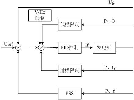
[0016] Unit 12 of Hebei Handan Thermal Power Plant, the generator model is QFSN-330-2, and the excitation regulator model is RCS9400. After the reactive power oscillation of the unit occurs, the judgment method of the present invention is applied to switch the mode. The reactive power of the generator is still oscillating from the automatic mode to the manual mode. Therefore, it is judged that the reactive power oscillation source is inside the excitation regulator . After the fault source is located, the generator shuts down, and the voltage measurement wiring of the excitation regulator is found to be loose after inspection. After tightening, it restarts and the reactive power oscillation subsides.

[0017] Therefore, the identification method of the present invention can accurately locate the working condition of the reactive power oscillation source in the excitation regulator.

Embodiment 2

[0019] The No. 1 unit of Hebei Huadian Yuhua Thermal Power Co., Ltd., the generator model is QFSN-330-2, and the excitation regulator is the UNITROL5000 type produced by ABB of Switzerland. After reactive power oscillation of the unit occurs, the judgment method of the present invention is applied to switch the mode from automatic mode to manual mode. The reactive power oscillation of the generator subsides, but the reactive power of the opposite substation is still oscillating. Therefore, it is judged that the source of the reactive power oscillation is outside the excitation regulator, that is, on the grid side. After the fault source was located, the inspection found that: the power plant had performed a removal operation on the low-voltage side reactive power compensation device of the main transformer at the opposite substation, causing reactive power oscillation.

[0020] Therefore, the identification method of the present invention can accurately locate the working conditi...


PUM


Abstract

The invention discloses a method for judging a reactive power oscillation source of a power grid. A key technology is that: the method comprises the following steps of: when reactive power oscillation in the running process of the power grid occurs, switching the control mode of an excitation regulator of a generator from an automatic control mode into a manual control mode, and making a judgment; and if reactive power fluctuates, determining hat the oscillation source is outside the excitation regulator and that the power grid fails, and if the reactive power stops fluctuating, determining that the oscillation source is in the excitation regulator. By the method, the reactive power oscillation source can be rapidly identified, so that a phenomenon that reactive power oscillation causes misoperation of a relay protection device, so the mistripping of a line is caused and the power failure accident of the power grid is caused can be avoided; and the routine is broken, the oscillation source can be identified according to the simple switching of the operating mode of the excitation regulator, so that an unexpected effect is achieved.

Description

Technical field [0001] The present invention relates to a measurement technology, in particular to a method for identifying the source of reactive power oscillation, which is used for checking the source of reactive power of the power grid and quelling the reactive power oscillation. Background technique [0002] The grid reactive power oscillation is one of the common faults in the power system. Identifying whether the reactive power oscillation source is inside or outside the excitation regulator of the generator is a difficult point to solve this fault. At present, the commonly used methods are mainly to increase or decrease the active power, increase the reactive power, and exit the power system stabilizer. These methods can change the generator's operating state to quell the reactive power oscillation. However, this method has a certain degree of blindness, which may further aggravate the oscillation of reactive power; each step of this method needs to be approved by the po...

Claims


Application Information

Patent Timeline
Patent Type & Authority Applications(China)
IPC IPC(8): H02J3/24
Inventor 孟凡超
Owner STATE GRID HEBEI ELECTRIC POWER RES INST
Learn More