Supercharge Your Innovation With Domain-Expert AI Agents!

Air compression and expansion system with single shaft compressor and turbine arrangement

A technology of compressor system and turbine system, which is applied to gas turbine devices, pump devices, mechanical equipment, etc., and can solve the problems of requiring many components and a large amount of space.

Inactive Publication Date: 2012-09-12
GENERAL ELECTRIC CO
View PDF6 Cites 1 Cited by
  • Summary
  • Abstract
  • Description
  • Claims
  • Application Information

AI Technical Summary

Problems solved by technology

For example, the arrangement of multiple drive shafts 104, 106 and clutches 108, 110 requires many components and a lot of space

Method used


Image

  • Air compression and expansion system with single shaft compressor and turbine arrangement
  • Air compression and expansion system with single shaft compressor and turbine arrangement
  • Air compression and expansion system with single shaft compressor and turbine arrangement

Examples


Embodiment Construction

[0020] According to an embodiment of the present invention, an air compression and expansion system is provided having a combined motor generator unit and a single drive shaft coupled to a compressor and an expander.

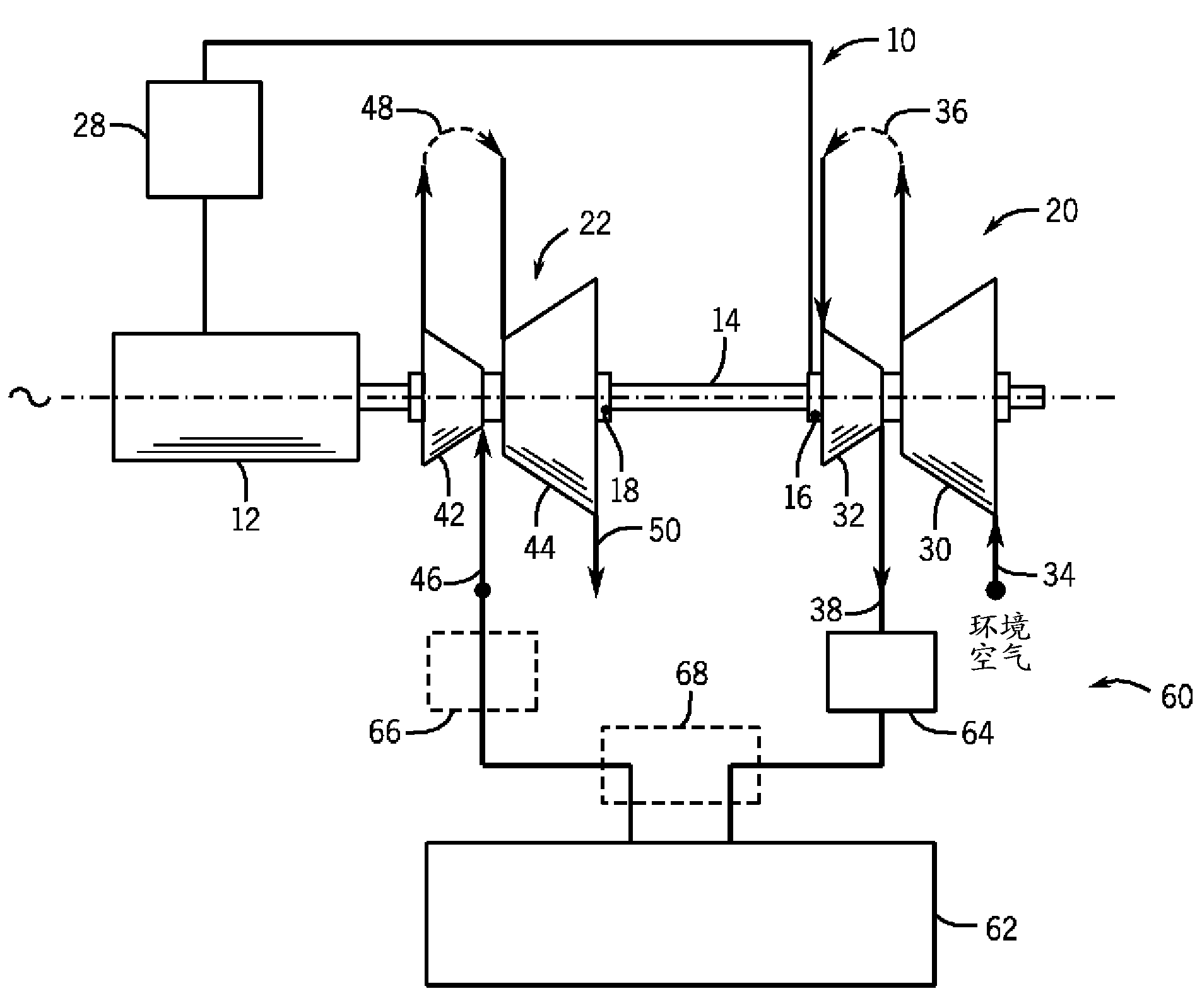
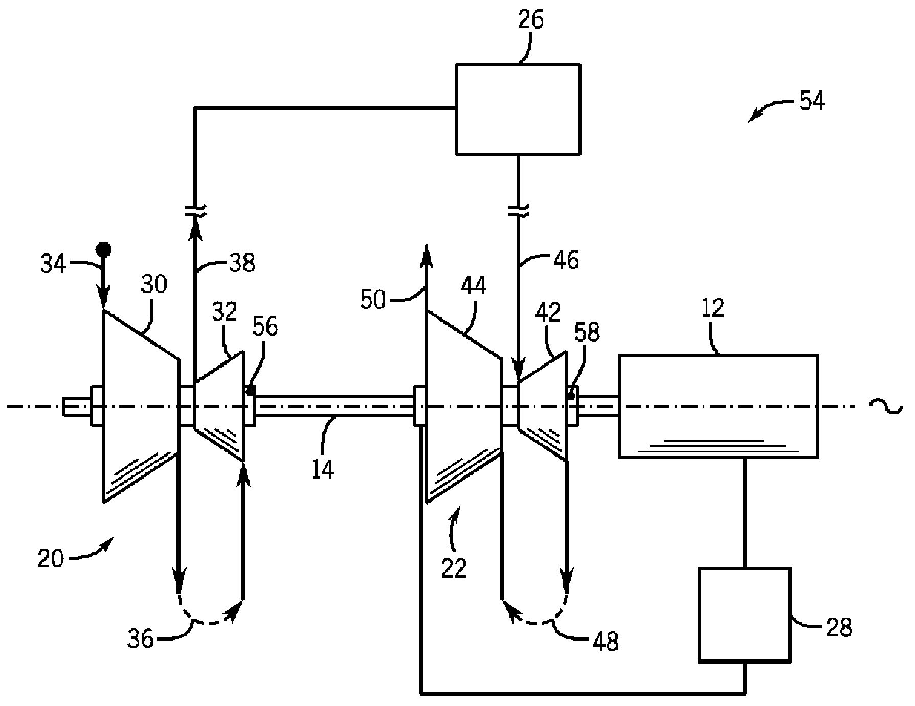
[0021] refer to figure 2 , shows an air compression and expansion system 10 according to an embodiment of the present invention. The air compression and expansion system 10 is configured to operate alternately in an operator-determined compression mode and an expansion mode. Air compression and expansion system 10 includes combined motor generator unit 12 , single drive shaft 14 , compressor clutch 16 and turbine clutch 18 , compressor system 20 and turbine system 22 . Such as figure 2 As shown in , the compressor system 20 and the turbine system 22 are each positioned coaxially about the drive shaft 14 and on the same side of the motor-generator unit 12 so that a single drive shaft can be employed in the air compression and expansion system 10 14. Similar...


PUM


Abstract

An air compression and expansion system having a combined motor-generator unit and a single drive shaft coupled to compressors and expanders is disclosed. The system includes a motor-generator unit, a drive shaft connected to the motor-generator unit configured to transmit rotational power to and from the motor-generator unit, a compressor system selectively coupleable to the drive shaft and positioned thereabout, and a turbine system selectively coupleable to the drive shaft and positioned thereabout, the turbine system positioned with the compressor system on a common side of the motor-generator unit. The air compression and expansion system also includes a compressor clutch attached to the compressor system and a turbine clutch attached to the turbine system. The compressor clutch and the turbine clutch are arranged coaxially about the drive shaft and configured to selectively couple and decouple the compressor system and the turbine system, respectively, to the drive shaft.

Description

technical field [0001] Embodiments of the present invention relate generally to air compression and expansion systems, and more particularly, to air compression and expansion systems having combined motor generator units and a single drive shaft coupled to a compressor and an expander. Background technique [0002] Air compression and expansion systems are used in many industries for a variety of applications. For example, one such application is the use of air compression and expansion systems as turbines in the production and storage of energy. Compressed air energy storage (CAES) systems typically include a compression train with multiple compressors that compress intake air and provide the compressed intake air to a cavern, underground storage, or other compressed air storage means. The compressed air is then used to drive a turbine to generate energy such as, for example, electricity. During operation of the compression stage of a CAES system, compressed intake air is...

Claims


Application Information

Patent Timeline
Patent Type & Authority Applications(China)
IPC IPC(8): F02C6/16F02C1/02F02C3/113F02C6/02F04D25/04F04D17/12
CPCF02C1/02F02C3/113F02C6/02F02C6/16F04D17/12F04D25/04Y02E60/16Y10T29/49245
Inventor S.W.弗罗伊恩德
Owner GENERAL ELECTRIC CO
Features
  • R&D
  • Intellectual Property
  • Life Sciences
  • Materials
  • Tech Scout
  • Unparalleled Data Quality
  • Higher Quality Content
  • 60% Fewer Hallucinations
Learn More