Integrated viscous clutch

A clutch and viscous technology, applied in clutches, fluid clutches, fluid-driven clutches, etc., can solve problems such as wire failures and shortened bearing life

Inactive Publication Date: 2012-09-12
HORTON
View PDF7 Cites 9 Cited by
  • Summary
  • Abstract
  • Description
  • Claims
  • Application Information

AI Technical Summary

Problems solved by technology

Any side load on the wires at the electrical interface

Method used


Image

  • Integrated viscous clutch
  • Integrated viscous clutch
  • Integrated viscous clutch

Examples


Embodiment Construction

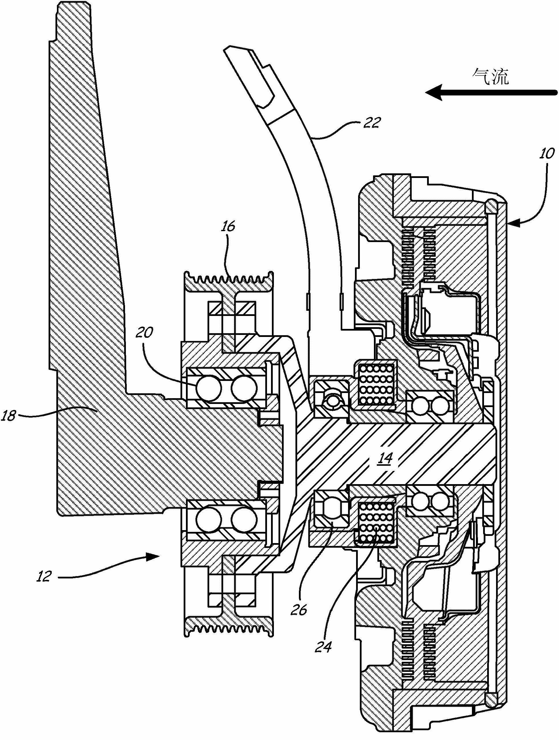
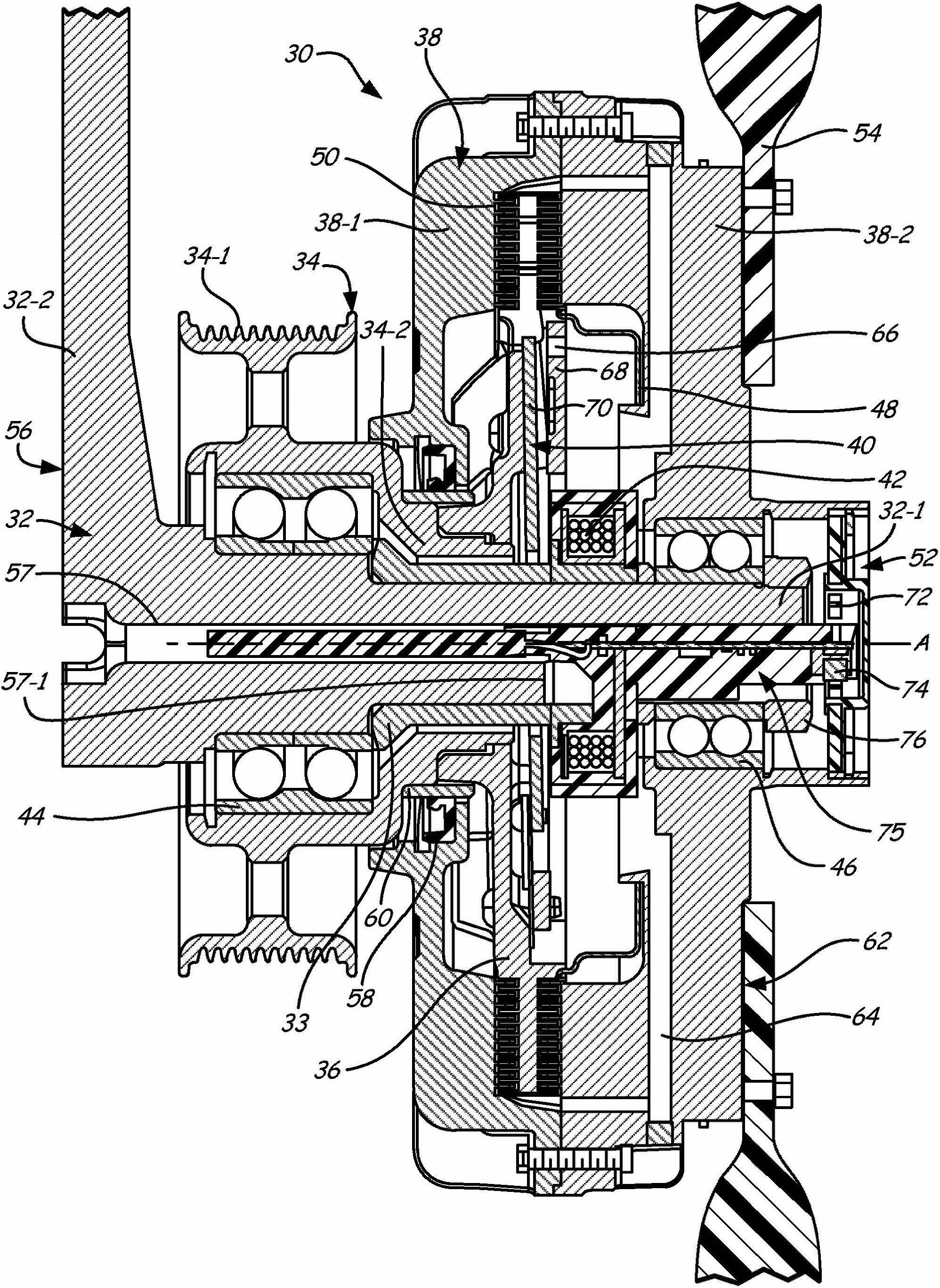
[0014] The present invention is a viscous clutch assembly that allows good packaging, power dissipation and system support and is suitable as a fan clutch in automotive applications. In general, a clutch (or driver) includes a mounting shaft (synonymously called a journal bracket) that may extend between the front and rear faces along the axial length of the clutch. Mounting shafts are designed to serve a variety of purposes, including providing support for fans, housings, rotors, pulleys (synonymously called sheaves) and solenoid coils, providing a conduit path for electrical control wires, and optionally A portion of the magnetic flux circuit for actuation of the valve is provided. All these functions are combined in the mounted shaft, allowing a very compact design and eliminating a considerable number of components compared to conventional viscous clutch and hub arrangements. In addition, the clutch of the present invention allows the electromagnetic coil to be positioned...


PUM


Abstract

A viscous clutch (30; 30') includes a stationary journal bracket (32; 32') defining a mounting shaft (32-1; 32-1'), an output member (34; 34') rotatably supported on the mounting shaft about an axis (A), an input member (34; 34') rotatably supported on the mounting shaft about the axis, and a working chamber (50; 50') defined between the input member and the output member to selectively transmit torque there between when a shear fluid is present. The mounting shaft extends axially through the viscous clutch from a front face (62; 62') of the viscous clutch to a rear face (56; 56') of the viscous clutch, with the rear face defining a mounting surface for mounting the viscous clutch at a mounting location. The front and rear faces are located at opposite sides of the viscous clutch and face in opposite directions.

Description

technical field [0001] The invention relates to a viscous clutch. Background technique [0002] Among other uses, viscous clutches are used in various automotive fan drive applications. These clutches use relatively thick silicone oil (commonly known as shear fluid or viscous fluid) for the selective transfer of torque between two rotating parts. Engaging or disengaging the clutch is possible by selectively allowing silicone oil to flow into and out of the clutch's working area between the input and output members (eg, the input rotor and the output housing). Valves are used to control the flow of silicone oil in the working area between the input and output. Recent clutch designs have been employed which allow silicone oil to be stored in the rotating input portion of the clutch when the clutch is disengaged to maintain kinetic energy available to the silicone oil to allow the clutch to engage rapidly from the closed state. This also allows the clutch to have very low ou...

Claims


Application Information

Patent Timeline
IPC IPC(8): F16D35/02F16D35/00
CPCF16D2300/18F16D35/024F16D25/02F16D35/00F16D35/02
Inventor 戴维·R·亨尼西托马斯·施密特斯科特·米勒
Owner HORTON
Why Eureka
Try Eureka