Ultrasound transducer for using in a fluid medium

一种流体介质、换能器的技术,应用在发声器械、测量流量/质量流量、液体/流体固体测量等方向,能够解决不利发现等问题

Inactive Publication Date: 2012-09-12
ROBERT BOSCH GMBH
View PDF8 Cites 10 Cited by
  • Summary
  • Abstract
  • Description
  • Claims
  • Application Information

AI Technical Summary

Problems solved by technology

However, a production challenge arises here: media can still enter the interior of the housing at the edge of the sealing membrane, which can be disadvantageously detected, for example, in flow measurement in internal combustion engines.

Method used


Image

  • Ultrasound transducer for using in a fluid medium
  • Ultrasound transducer for using in a fluid medium
  • Ultrasound transducer for using in a fluid medium

Examples


Embodiment Construction

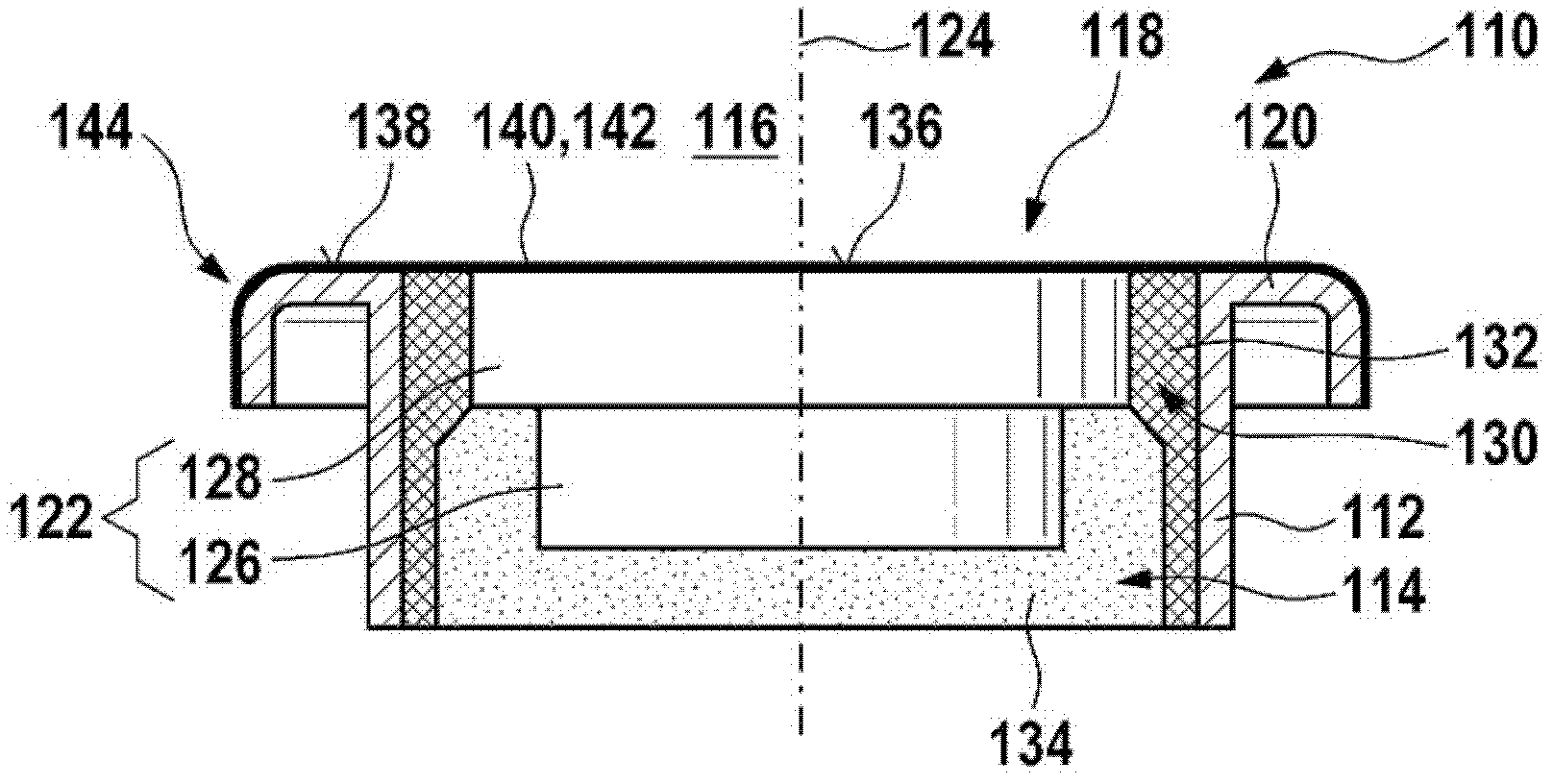
[0029] exist figure 1 An exemplary embodiment of an ultrasound transducer 110 according to the prior art is shown in a sectional view. Ultrasonic transducer 110 may, for example, substantially correspond to the ultrasonic transducer disclosed in DE 10 2008 055 126.0. However, other configurations are also possible. Ultrasonic transducer 110 includes a housing 112 which is only partially shown in the exemplary embodiment shown. The housing 112 is substantially sleeve-shaped and has an interior 114 . The interior 114 in turn has an opening 118 on its side facing the fluid medium 116 , which can have, for example, a circular or polygonal cross section. The opening 118 is annularly surrounded by a housing edge 120 which, in the exemplary embodiment shown, is bent back away from the fluid medium 116 .

[0030] In the illustrated exemplary embodiment, a transducer core 122 is accommodated within interior space 114 , for example coaxially to axis 124 of ultrasound transducer 110 ...


PUM


Abstract

The invention relates to an ultrasound transducer (110) for using in a fluid medium (116). The ultrasound transducer (110) comprises at least one housing (112) having at least one inner space (114), and at least one transducer core (118) received in the inner space (114) and comprising at least one electric-acoustic transducer element (126). The housing (112) comprises at least one opening (118) facing the fluid medium (116) and at least partially covered by at least one sealing film (142). An edge of the sealing film (142) is sealed by at least one sealing material (164).

Description

Background technique [0001] Different types of ultrasonic transducers are known from the prior art for use in fluid media. An ultrasonic transducer is here generally understood to be an element which is capable of emitting ultrasonic signals into a fluid medium and / or receiving ultrasonic signals from a fluid medium and converting them, for example, into electrical signals. Such ultrasonic transducers are used, for example, in ultrasonic flow meters in process technology and / or in the automotive sector, for example in flow meters (Ultrasonic Flow Meter, Ultrasonic Flow Meter, UFM), especially in intake manifolds of internal combustion engines. and / or in the exhaust manifold. Examples of such ultrasonic transducers are disclosed in DE 10 2007 010 500 A1, DE 10 2007 037 088 A1 or in the later published German patent application number DE 10 2008 055 126.0 of the same family of the applicant of the present invention. The ultrasonic transducers described here can basically also ...

Claims


Application Information

Patent Timeline
Patent Type & Authority Applications(China)
IPC IPC(8): G01F1/66G10K9/22
CPCG10K9/122G01F23/296G01F23/2968G10K9/22
Inventor R·米勒G·许夫特尔M·赫斯特布林克T·朗S·拉德万B·金茨R·万贾
Owner ROBERT BOSCH GMBH
Why Eureka
Try Eureka