Dust removal device and high-temperature waste gas treatment equipment

A technology of dust removal device and airflow, which is applied in transportation and packaging, chemical instruments and methods, dispersed particle separation, etc., can solve the problem of not taking into account the balanced use of ceramic filter tube filtration resources, etc., to improve filtration efficiency and improve backwashing. Efficiency, uniform thickness effect

Active Publication Date: 2019-02-01
BGT GRP CO LTD
View PDF7 Cites 9 Cited by
  • Summary
  • Abstract
  • Description
  • Claims
  • Application Information

AI Technical Summary

Problems solved by technology

However, it does not take into account how to fully and evenly utilize the filtration resources of ceramic filter tubes

Method used


Image

  • Dust removal device and high-temperature waste gas treatment equipment
  • Dust removal device and high-temperature waste gas treatment equipment
  • Dust removal device and high-temperature waste gas treatment equipment

Examples


Embodiment 1

[0048] This embodiment discloses a dust removal device. In the case of no conflict or contradiction, the whole and / or part of the content of the preferred implementations of other embodiments can be used as a supplement to this embodiment.

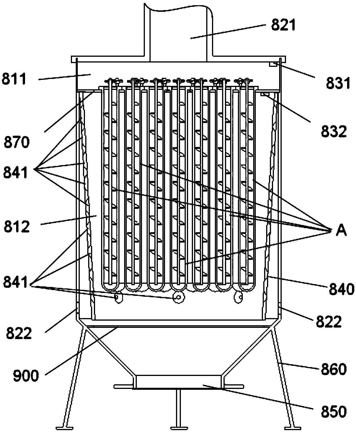
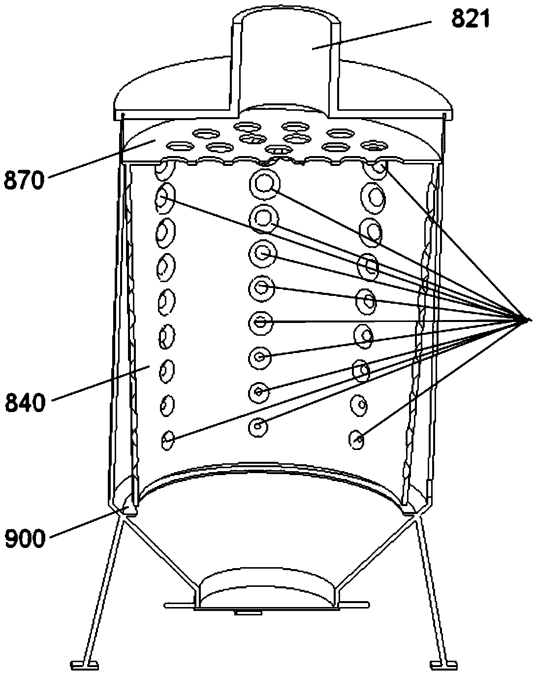
[0049] According to a preferred embodiment, a dust removal device, see figure 1 , 2 and 3 may include a hollow shell and a partition 870 disposed inside the shell. The partition 870 at least separates the first chamber 811 and the second chamber 812 formed by the housing. A plurality of ceramic filter pipes A may be vertically arranged side by side on the partition 870 . The dedusting device can be configured as gas flowing from the first chamber 811 to the second chamber 812 or from the second chamber 812 to the first chamber 811 must be filtered by the ceramic filter structure. The ceramic filter structure may include a ceramic filter tube A, and the ceramic filter tube A may include a tube body 100 of ceramic fibers for filtering. T...

Embodiment 2

[0057] This embodiment can be a further improvement on Embodiment 1. In the case of no conflict or contradiction, the whole and / or part of the content of preferred implementations of other embodiments can be used as a supplement to this embodiment.

[0058] According to a preferred embodiment, a dust removal device may include a hollow shell and a partition 870 disposed inside the shell. The housing may be divided into a first chamber 811 and a second chamber 812 by a partition 870 . Several ceramic filter tubes A may be provided on the partition 870 . The dedusting device may be configured such that the gas must pass through the wall of the ceramic filter tube A when flowing from the first chamber 811 to the second chamber 812 or from the second chamber 812 to the first chamber 811 . The ceramic filter tube A may include a tube body 100 of ceramic fibers for filtering. Two-way air communication is realized between the inside of the tube body 100 and the outside of the tube ...

Embodiment 3

[0064] This embodiment can be further improved on the points of Embodiment 1 and / or 2. This embodiment discloses a high-temperature exhaust gas treatment equipment, which adopts the dust removal device E of the present invention. In the case of no conflict or contradiction, the whole and / or part of the content of the preferred implementations of other embodiments may serve as supplements to this embodiment.

[0065] According to a preferred embodiment, a high-temperature exhaust gas treatment equipment includes a deacidification device C and a denitrification device D, and the high-temperature exhaust gas treatment equipment also includes a dust removal device E in one of the aforementioned modes; wherein, the dust removal device E is in air communication with the combustion chamber B, And before the exhaust gas reaches the dust removal device E, the filtered air flow formed by the flow of the waste gas passes through the deacidification treatment of the deacidification device ...


PUM


Abstract

The invention relates to a dust removal device, which comprises a hollow shell and a partition disposed in the shell. The partition at least divides the shell into a first chamber and a second chamber. Several ceramic filter pipes are vertically arranged side by side on the partition. The dust removal device is designed as follows: the gas flows from the first chamber to the second chamber or fromthe second chamber to the first chamber and must be filtered through a ceramic filtering structure. The ceramic filtering structure comprises the ceramic filter pipes, which comprises ceramic fiber pipes used for filtration. The two-way air passage between the inside of the pipes and the outside of the pipes is realized through several air vents on the pipe wall of the pipes. The dust removal device is arranged according to the following mode: the filtered gas that enters the second chamber can flow from at least two different levels to the several ceramic filter pipes. According to the dustremoval device, the filter resources of the ceramic filter pipes can be more fully and evenly utilized, thus enhancing the filter efficiency and being helpful for improving the backwash efficiency.

Description

technical field [0001] The invention relates to the field of processing high-temperature waste gas containing dust, in particular to a dust removal device and high-temperature waste gas processing equipment. Background technique [0002] The problem of air pollution has become a hot spot and focus of environmental protection that people pay close attention to, and it is an ecological and technical problem that people all over the world have to solve. Metallurgy, electric power, building materials and other industrial kilns will emit a large amount of dusty fume during production, which will not only have a huge impact on air quality and visibility, but also the fine particles in it will cause great damage to the respiratory system, seriously threatening people's health. healthy. Therefore, the purification and dust removal of flue gas has become a necessary measure in industrial production. [0003] In order to remove dust, most factories are now equipped with dust removal...

Claims


Application Information

Patent Timeline
Patent Type & Authority Applications(China)
IPC IPC(8): B01D46/24B01D46/00
CPCB01D46/2407B01D46/2411B01D46/66B01D46/64
Inventor 权秋红田瑞昌刘勇锋仝中聪
Owner BGT GRP CO LTD
Why Eureka
Try Eureka