

Connector terminal
A technology of connector terminals and connection terminals, which is applied in the direction of connections, parts of connection devices, protective grounding/shielding devices of connection parts, etc., can solve problems such as increased heat, sparks and explosions on contacts, and achieve insertion force Minimize, eliminate the effects of explosions and prevent sparks
- Summary
- Abstract
- Description
- Claims
- Application Information
AI Technical Summary
Problems solved by technology
Method used
Image

Examples
Embodiment Construction
[0029] Preferred embodiments of the present invention will now be described in detail with reference to the accompanying drawings. Hereinafter, a detailed description of well-known functions and configurations incorporated herein will be omitted when it may make the subject matter of the present invention rather unclear.
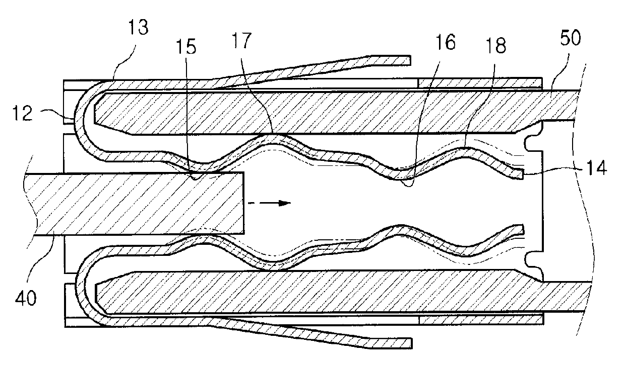
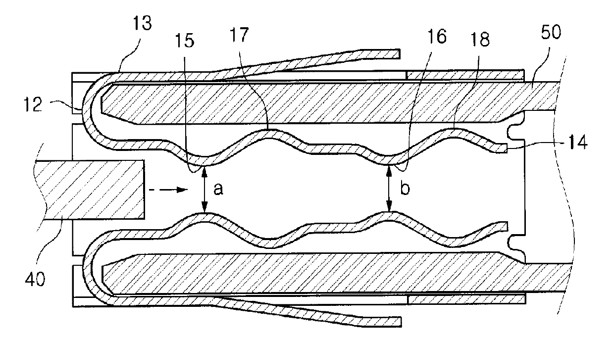
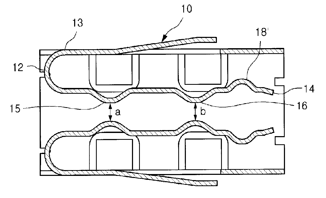
[0030] figure 1 is a perspective view illustrating a connector terminal according to the present invention, and figure 2 is a partial view illustrating an embodiment of the connector terminal according to the present invention.
[0031] Such as figure 1 As shown, the connector terminal 30 is configured such that the connecting body terminal unit 50 is inserted into one side of the coupling terminal unit 10 formed in a pipe shape opened at its opposite ends, and the connecting terminal unit 40 is inserted into the coupling terminal The other side of the unit 10 is so as to form the contacts 15 , 16 , 17 and 18 , and the connection body terminal unit 50 an...
PUM
 Abstract
Description
Claims
Application Information