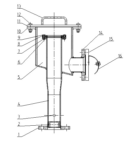
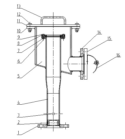
Vertical foam generator
A generator and foam technology, applied in fire rescue and other directions, can solve the problems of inconvenient installation and affecting the effect of foam, and achieve the effect of convenient installation, simple maintenance and repair, and light weight
Inactive Publication Date: 2012-09-19
JIANGXI RONGHE SPECIAL FIRE EQUIP MFG
View PDF0 Cites 3 Cited by
- Summary
- Abstract
- Description
- Claims
- Application Information
AI Technical Summary
Problems solved by technology
When installing the vertical generator of this structure, the inlet part is generally installed at the bottom of the oil tank, while the buffer part and the deflector part are installed on the top of the tank, so that the inlet part and the buffer part must pass through the pipeline. It is very inconvenient to install like this; in addition, because the outlet, sealing sheet, shroud, etc. of this vertical foam generator are installed on the top of the tank, while the nozzle, air suction device, etc. are installed on the bottom, so If the foam mixture is sprayed out through the nozzle, it must go through a vertical height of more than ten meters to reach the outlet position, that is to say, the pressure loss from the nozzle to the outlet generator is at least more than 0.1MPa, which will seriously affect the effect of foam generation.
Method used
View moreImage
Smart ImageViewing Examples
Examples
Embodiment Construction
Login to View More PUM
| Property | Measurement | Unit |
|---|---|---|
| Length | aaaaa | aaaaa |
Abstract
The invention relates to a vertical foam generator and belongs to the field of industrial fire control. The invention aims to provide the vertical foam generator. The installation of the foam conduit part of the vertical foam generator is simplified. The vertical foam generator comprises a foam conduit, a buffer tube and a guide plate, wherein the foam conduit partially extends into the inner cavity of the buffer tube; the outer wall of the buffer tube and the outer wall of the foam conduit are welded, and the outer wall of the foam conduit and the outer wall of the buffer tube form a hollow cavity body; the side wall of the buffer tube is provided with a hole; the buffer tube is connected with a mounting flange fixedly arranged on a holed storage tank wall through a discharge flange; and the guide plate and the mounting flange are fixedly connected. Compared with the prior art, the vertical foam generator has the following advantages: 1-, the generator is smaller in size, lighter in weight and more convenient in installation after the inlet of the generator and the buffer tube are combined into a whole; 2-, the fire-fighting efficiency is higher; and 3-, the maintenance is simple.
Description
technical field [0001] The invention relates to a vertical foam generator, which belongs to the field of industrial fire protection. Background technique [0002] The foam generator is a foam generating device installed on the top of a large oil tank, and it is a liquid spray fire extinguishing device. There are many horizontal foam generators on the market, but there are not many vertical foam generators. Most of the vertical foam generators on the market are split, which are divided into three parts: the first part is imported. The second part is the buffer part, which is mainly composed of the buffer tube, the sealing piece, and the body connection part; the third part is the deflector part, which mainly includes the installation method Blue, shroud and other components. When installing the vertical generator of this structure, the inlet part is generally installed at the bottom of the oil tank, while the buffer part and the deflector part are installed on the top of...
Claims
Login to View More Application Information
Patent Timeline
 IPC IPC(8): A62C5/02
Inventor 廖建华
Owner JIANGXI RONGHE SPECIAL FIRE EQUIP MFG
Features
- R&D
- Intellectual Property
- Life Sciences
- Materials
- Tech Scout
- Unparalleled Data Quality
- Higher Quality Content
- 60% Fewer Hallucinations
Learn More Browse by: Latest US Patents, China's latest patents, Technical Efficacy Thesaurus, Application Domain, Technology Topic, Popular Technical Reports.
© 2025 PatSnap. All rights reserved.Legal|Privacy policy|Modern Slavery Act Transparency Statement|Sitemap|About US| Contact US: help@patsnap.com


