Process for machining molding core

A processing technology and core technology, which is applied in the processing technology of injection mold cores and workpiece processing technology, can solve the problems of reducing the service life of molds, scrapping cores, and wasting materials, so as to improve processing accuracy and ensure the same Axis, the effect of avoiding scrap rate

Inactive Publication Date: 2013-08-14
SUZHOU YAER PLASTIC TECH
View PDF6 Cites 0 Cited by
  • Summary
  • Abstract
  • Description
  • Claims
  • Application Information

AI Technical Summary

Problems solved by technology

For most cores, its structure is as attached figure 1 As shown in , there is an irregularly shaped cavity 1 inside and irregularly shaped outside. During processing, because the length of the core is relatively long, and its internal cavity and shape are very irregular, after processing core, the coaxiality of the inner cavity and the outer surface has a large deviation, and the rework rate is quite large
For some injection molded parts with high precision requirements, these cores with deviations in coaxiality may be scrapped, wasting a lot of materials
In addition, if the processed cores have deviations, it is available for products that do not require high precision. However, with the increase in the number of mold opening and closing, these deviations will also make other inserts or inserts that match it Inserts and other parts are damaged, which reduces the service life of the mold and greatly increases the maintenance cost of the mold

Method used


Image

  • Process for machining molding core
  • Process for machining molding core

Examples


Embodiment Construction

[0015] The present invention is described below in conjunction with accompanying drawing.

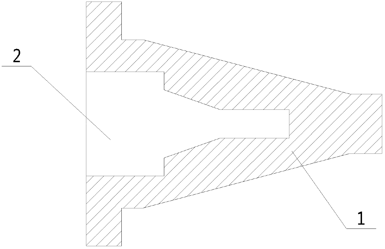
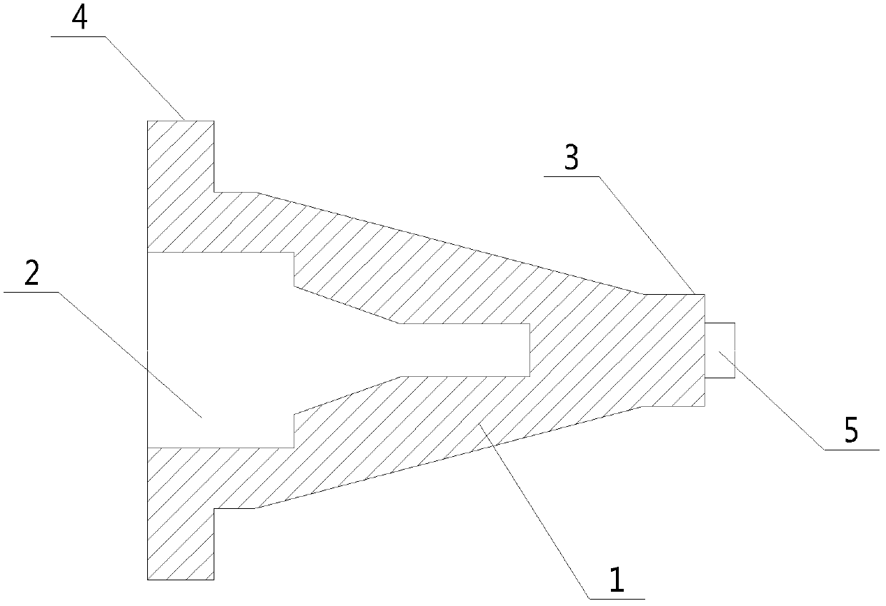
[0016] as attached figure 2 Shown, core processing technology of the present invention comprises the following steps:

[0017] Clamp the core blank, process the first reference surface 3 of the core 1 at the right end of the core 1, and process a cylindrical process terminal 5 with a length of 20mm or 25mm on the end surface of the reference;

[0018] Clamp the core 1 with the first datum plane 3 as the reference, process the inner cavity 2 located at the left end of the core 1, and process the second datum plane 4 on the left end of the core 1;

[0019] The core 1 is clamped with the second datum plane 4 as the reference, and the tail end of the process terminal 5 is supported by the tip to process the outer contour of the core 1, and finally the process terminal 5 is cut off to complete the core processing.

[0020] Adopting the technological method of the present invention, using ...


PUM

PropertyMeasurementUnit
lengthaaaaaaaaaa

Abstract

The invention discloses a process for machining a molding core. The method comprises the following steps: clamping a molding core blank, machining a first reference plane of the molding core at one end of the molding core, and machining a cylindrical process terminal on the end face of the first reference plane; clamping the molding core with the first reference plane as reference, machining an inner cavity of the molding core, and machining a second reference plane at the other end of the molding core; clamping the molding core with the second first reference plane as reference, supporting the tail end of the process terminal with a core clamper, machining an outer profile of the molding core, and finally cutting the process terminal to complete the machining of the molding core. The process machines the molding core by use of the two reference planes on the molding core, so as to prevent the radial run out of the molding core during the machining of the outer profile, ensure the coaxiality of the inner cavity and the outer profile of the molding core, improve the machining precision of the molding core and avoid rejection of the molding core during machining.

Description

technical field [0001] The invention relates to a processing technology of a workpiece, in particular to a processing technology of a core on an injection mold, and belongs to the technical field of injection mold spare parts processing. Background technique [0002] In the injection mold, because the injection molded parts to be processed are various, the cores in the injection mold are also different. For most cores, its structure is as attached figure 1 As shown in , there is an irregularly shaped cavity 1 inside and irregularly shaped outside. During processing, because the length of the core is relatively long, and its internal cavity and shape are very irregular, after processing The core of the core has a large deviation in the coaxiality of the inner cavity and the outer surface, and the rework rate is quite large. For some injection molded parts with high precision requirements, these cores with deviations in coaxiality may be scrapped, wasting a lot of material. ...

Claims


Application Information

Patent Timeline
Patent Type & Authority Patents(China)
IPC IPC(8): B23P15/24
Inventor 沈冬林
Owner SUZHOU YAER PLASTIC TECH
Why Eureka
Try Eureka