
Composite sand mould forming process for producing casting fireproof materials

A technology for melting and casting refractory materials and molding process, which is applied in the field of melting and casting refractory materials, and can solve the problems of easy cracking of products and easy collapsing boxes, so as to achieve the effects of improving quality, saving energy and solving easy collapsing boxes.

Active Publication Date: 2012-09-19
RUITAI MATERIALS TECHNOLOGY CO LTD +1
View PDF4 Cites 7 Cited by
  • Summary
  • Abstract
  • Description
  • Claims
  • Application Information

AI Technical Summary

Problems solved by technology

[0006] In order to solve the above-mentioned technical problems existing in the prior art, the object of the present invention is to provide a composite sand molding process for producing fusion-casting refractory materials. The technical problems that the box is easy to collapse and the product is easy to crack in the material process

Method used


Image

  • Composite sand mould forming process for producing casting fireproof materials
  • Composite sand mould forming process for producing casting fireproof materials
  • Composite sand mould forming process for producing casting fireproof materials

Examples


Embodiment 1

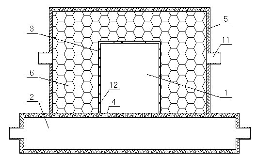
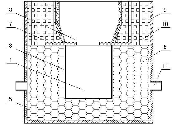
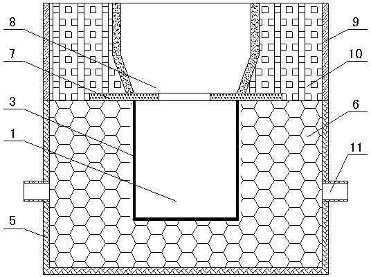
[0023] This example exemplarily illustrates the production of composite sand molds of fused-cast zirconium corundum products of 250×400×1200 mm. Refer to attached Figure 1-2 As shown, the composite sand mold is prepared through the following steps:

[0024] Riser 8 adopts thermal insulation heating element to make template (containing 2.2-3.5 wt% silicon fiber, 72-85wt% quartz sand, 2.5-5.0wt% aluminum powder, 2.5-6.0wt% ferric oxide, 1.2 -2.5 manganese dioxide, 0.8-1.5wt% furan resin and 0.6-1.5wt% phenolic resin), according to the drawing shape set by the process, 400 (high) × 400 × 40mm (thick) (2 pieces) And 400 (height) × 250 × 40 mm (thickness) (2 pieces) thermal insulation and heating body boards, which are fastened and assembled together with steel wires with a diameter of 2mm.

[0025] A hollow negative pressure forming model 1 (dimensions 250×400×1200 mm) will be made according to the shape of the product (a metal model, such as an aluminum or aluminum alloy model...

Embodiment 2

[0030] This embodiment exemplarily illustrates the production of composite sand molds of fused-cast zirconium corundum products of 250×400×1200 mm, refer to the attached Figure 1-2 As shown, the composite sand mold is prepared through the following steps:

[0031] Riser 8 adopts resin sand mold riser 8 (furan resin 3wt%, quartz sand 97wt%), according to the drawing shape set by the process, the internal shape of riser 8 made of resin sand mold is 600 (height) × 400 × 250mm, The wall thickness around the riser 8 is 30mm.

[0032] A hollow negative pressure forming model 1 (dimensions 250×400×1200 mm) will be made according to the shape of the product, connected to the vacuum pumping chamber 2, and a softening heating device will be used to soften the EVA film 3 (EVA with a vinyl acetate content of 32wt%) Plastic film) is softened and covered on the outer surface of the model 1, and the air in the special model 1 and between the special film 3 and the special model 1 is re...


PUM


Abstract

The invention relates to a composite sand mould forming process for producing casting fireproof materials. The composite sand mould forming process includes steps of: mould preparing; laminating; mould vacuumizing; box containing; thermal insulation material filling; jolt ramming; vacuumizing of a thermal insulation box; pattern withdrawing; turning; feeder head placing; thermal insulation material filling on the periphery of a feeder head and the like. The composite sand mould forming process well solves the technical problems of easy box crush and crack of finished products caused by the fact that the negative pressure forming process is applied to the process of fireproof material casting. The composite sand mould manufactured by the composite sand mould forming process is applied to manufacturing of the casting fireproof materials, and the composite sand mould forming process is energy-saving and environment-friendly and improves appearance quality of the finished products.

Description

technical field [0001] The invention belongs to the technical field of melting and casting refractory materials, more specifically, the invention relates to a composite sand molding process for producing melting and casting refractory materials. Background technique [0002] Fused and cast refractory products are important lining materials for melting furnaces in the glass industry. The models used in the production of fused and cast refractories mainly include graphite molds, resin-bonded quartz sand sand molds and water glass-bonded quartz sand sand molds. Graphite molds are expensive and difficult to process; resin-bonded quartz sand molds are self-hardening at room temperature, easy to make integral sand molds, and have high precision in product appearance and size, but the sand mold has high technical content and costs higher than water glass; water glass The combined quartz sand sand mold has low technical content, is easy to manufacture, and has low cost, but its disa...

Claims


Application Information

Patent Timeline
Patent Type & Authority Applications(China)
IPC IPC(8): B28B1/087B28B1/52B28B1/54C04B35/657
CPCB22F7/06B28B1/54C22C29/12B28B1/087B28B1/52C04B35/657C04B35/484C04B35/109C04B2235/3217
Inventor 冯中起龙希成陈龙张鑫罗凯罗峰
Owner RUITAI MATERIALS TECHNOLOGY CO LTD
Learn More