

CAN (Controller Area Network) bus system and fault diagnosis method thereof
A CAN bus, fault technology, applied in the direction of bus network, data exchange through path configuration, circuit or fluid pipeline, etc., can solve the problem of wasting driver's time, achieve the effect of solving fault problems and convenient and fast fault diagnosis
- Summary
- Abstract
- Description
- Claims
- Application Information
AI Technical Summary
Problems solved by technology
Method used
Image

Examples
Embodiment Construction
[0028] The specific implementation manners of the present invention will be further described in detail below in conjunction with the accompanying drawings and embodiments. The following examples are used to illustrate the present invention, but are not intended to limit the scope of the present invention.
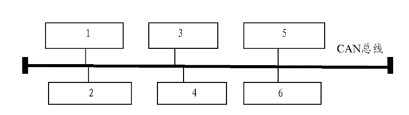
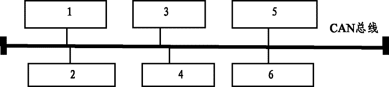
[0029] figure 1 It is the structural representation of the CAN bus system of the embodiment of the present invention; figure 1 Said, the CAN bus system includes at least one functional control system and instrument 6 connected to the CAN bus;
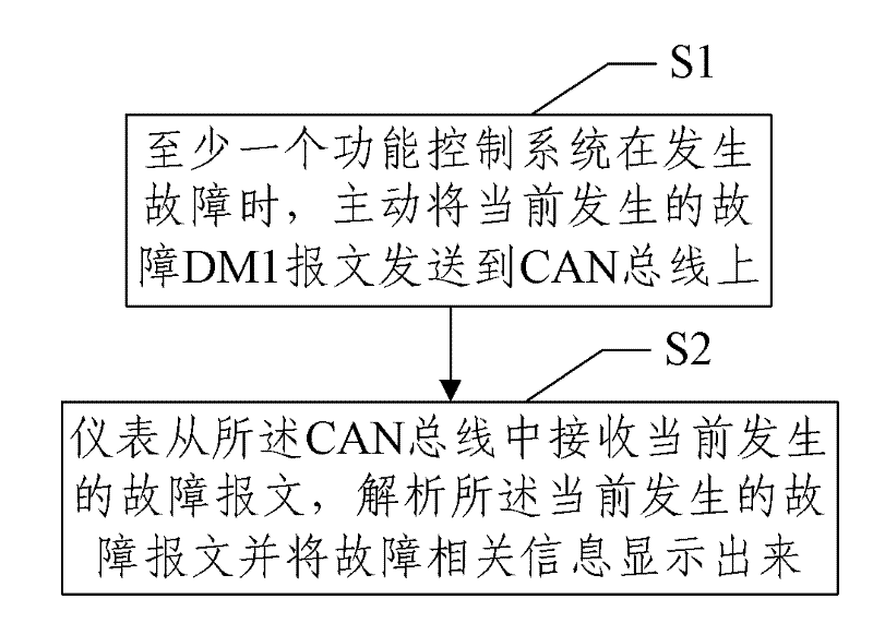
[0030] The at least one functional control system is further used to actively send the current fault message, that is, the DM1 message, to the CAN bus when a fault occurs;
[0031] The instrument 6 is further configured to receive a currently occurring fault message from the CAN bus, analyze the currently occurring fault message and display fault related information.
[0032] The at least one functional control system is further ...
PUM
 Abstract
Description
Claims
Application Information