
The transmission structure of the winding spindle on the winding machine

A technology of transmission structure and winding machine, applied in the field of transmission structure, can solve the problems of short service life, large operation noise, decreased operation stability, etc., and achieve the effects of reducing wear and noise, prolonging service life and stable winding operation.

Inactive Publication Date: 2015-09-09
NIDE MECHANICAL EQUIP
View PDF5 Cites 0 Cited by
  • Summary
  • Abstract
  • Description
  • Claims
  • Application Information

AI Technical Summary

Problems solved by technology

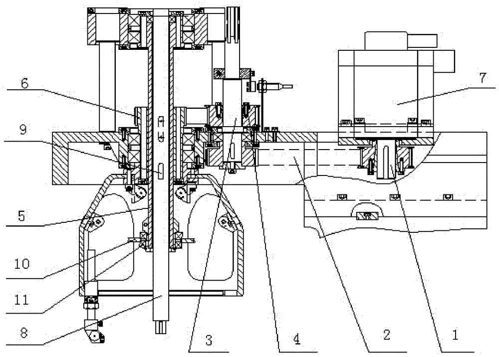
[0004] As mentioned above, the eccentric shaft 8 and the winding main shaft 5 rotate with the motor 7 at high speed when winding. Larger, the transmission structure is easy to wear, and the service life is not long. On the other hand, the winding mold located under the eccentric shaft 8 and installed on the winding main shaft 5 has a large vibration, which also produces a lot of noise and reduces the operation stability.

Method used


Image

  • The transmission structure of the winding spindle on the winding machine
  • The transmission structure of the winding spindle on the winding machine
  • The transmission structure of the winding spindle on the winding machine

Examples


Embodiment 1

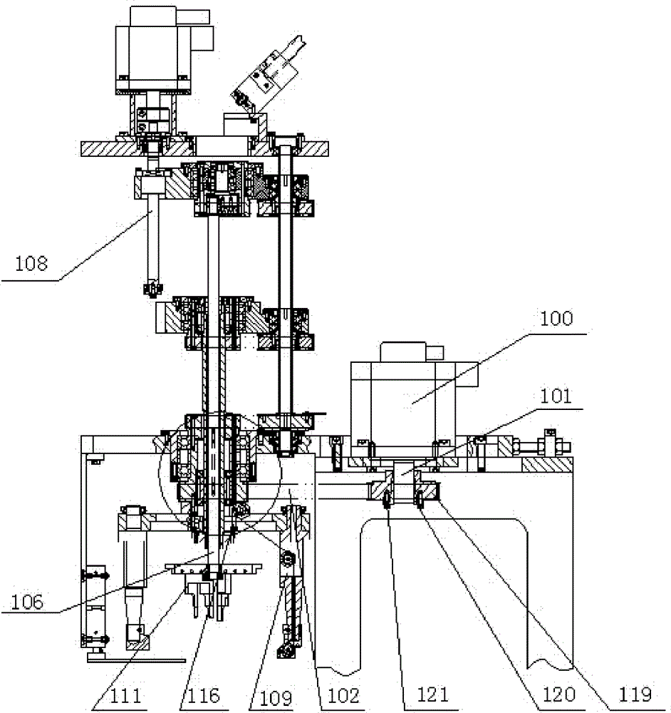
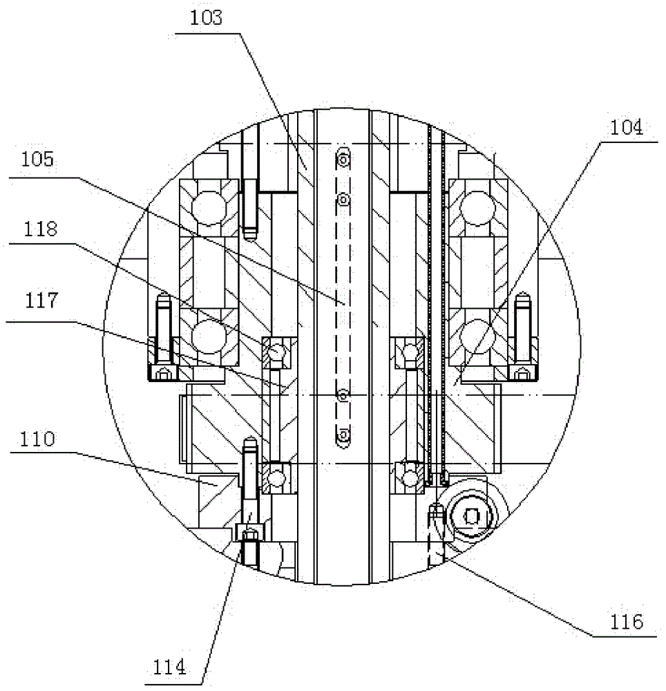
[0022] Example 1: see figure 2 , 3 As shown, a transmission structure of a winding spindle on a winding machine includes a servo motor 100, a timing belt 102 connected to the output shaft 101 of the servo motor, and the timing belt 102 is connected to a spindle synchronization wheel 104 provided on the winding spindle 103 , The winding spindle 103 is connected to the eccentric shaft 106 via a sliding key 105, the spindle synchronization wheel 104 is connected to the winding spindle 103 via a bearing assembly, and the top of the eccentric shaft 106 is fixedly installed in the head lifting mechanism 108 , The winding assembly 109 is connected to the spindle synchronization wheel 104 via the winding arm connecting seat 110, the winding mold assembly 111 is mounted on the eccentric shaft 106, and the winding arm connecting seat 110 is provided with the spindle The connection hole connected to the synchronization wheel 104 and the screw hole connected to the winding assembly 109. Th...


PUM


Abstract

The invention discloses a transmission structure of a winding main shaft on a winding machine, which comprises a motor and a synchronous belt connected with a motor output shaft. The synchronous belt is connected with a main shaft synchronous wheel arranged on the winding main shaft; and the winding main shaft is connected with an eccentric shaft through a key. The transmission structure is characterized in that the main shaft synchronous wheel is connected with the winding main shaft through a bearing assembly; the top end of the eccentric shaft is fixedly installed in a machine head lifting mechanism; a winding component is connected with the main shaft synchronous wheel through a winding arm connecting seat; and a winding mould component is installed on the eccentric shaft. The transmission structure has the advantages that the motor in the transmission structure drives the main shaft synchronous wheel to rotate through the synchronous belt, and the winding main shaft and the eccentric shaft do not rotate, so that the abrasion and the noise caused by the high-speed rotation are reduced, and the service life is prolonged; and meanwhile, the winding mould is installed on the fixed eccentric shaft, so that the vibration generated by rotation is reduced, and the operation stability is improved.

Description

technical field [0001] The invention relates to an induction coil winding machine, in particular to a transmission structure of a winding main shaft on the winding machine. Background technique [0002] In the production process of the motor, the first process is winding. Select a suitable wire-covered flat wire with a voltage level, and wind it on the winding machine to form a shuttle-shaped loop. The winding can be single flat winding or single vertical winding. It can also be double-flat transposition winding, or double-flat transposition vertical winding, which is determined according to specific requirements. [0003] No matter what kind of winding machine it is, usually a motor drives the winding main shaft through a transmission mechanism such as a gear or a synchronous belt, and the winding assembly installed under the winding main shaft rotates at a high speed. The wire comes out from the winding rod outlet mechanism in the winding assembly, and is wound on the win...

Claims


Application Information

Patent Timeline
Patent Type & Authority Patents(China)
IPC IPC(8): B65H79/00
Inventor 李胜权
Owner NIDE MECHANICAL EQUIP
Learn More