Columnar combustion arm guardrail

A guardrail and column type technology, which is applied to drilling equipment, earthwork drilling, support devices, etc., can solve the problems of insecurity, time-consuming and laborious, insertion, etc., and achieve the effect of reducing labor intensity, simple retracting and unloading operations, and protecting the guardrail.

Active Publication Date: 2012-09-19
CHINA NAT OFFSHORE OIL CORP +2
View PDF5 Cites 0 Cited by
  • Summary
  • Abstract
  • Description
  • Claims
  • Application Information

AI Technical Summary

Problems solved by technology

[0003] Above-mentioned various hard guardrails, when the combustion arm 14 needs to be packed up on the fixed frame 16, all guardrails 10 must be pulled down completely (as image 3 As shown), look for another place to store; when the combustion arm 14 is working again, reinstall the guardrail 10 on the combustion arm 14, so it is not only time-consuming and laborious, but also requires a storage space, which is not safe
like Figure 4 , Figure 5 As shown, if the guardrail 10 and the combustion arm 14 are stowed together on the groove holder body 17, the size of the groove holder body 17 needs to be increased, and the increase of the size of the groove holder body 17 will hinder the personnel on the platform. The arrangement of walking and other equipment, sometimes the combustion arm 14 is also forced to be set outside the ship's side
Especially when the combustion arm 14 and the guardrail 10 are fixed together on the slotted frame body 17, if the guardrail 10 is slightly deformed, the two cannot be inserted together on the slotted frame body 17. The disadvantages are: one is the slotted frame body 17 The structure is relatively complicated, and the second is that the guardrail 10 is slightly deformed and cannot be placed in place

Method used


Image

  • Columnar combustion arm guardrail
  • Columnar combustion arm guardrail
  • Columnar combustion arm guardrail

Examples


Embodiment Construction

[0021] The present invention will be described in detail below in conjunction with the accompanying drawings and embodiments.

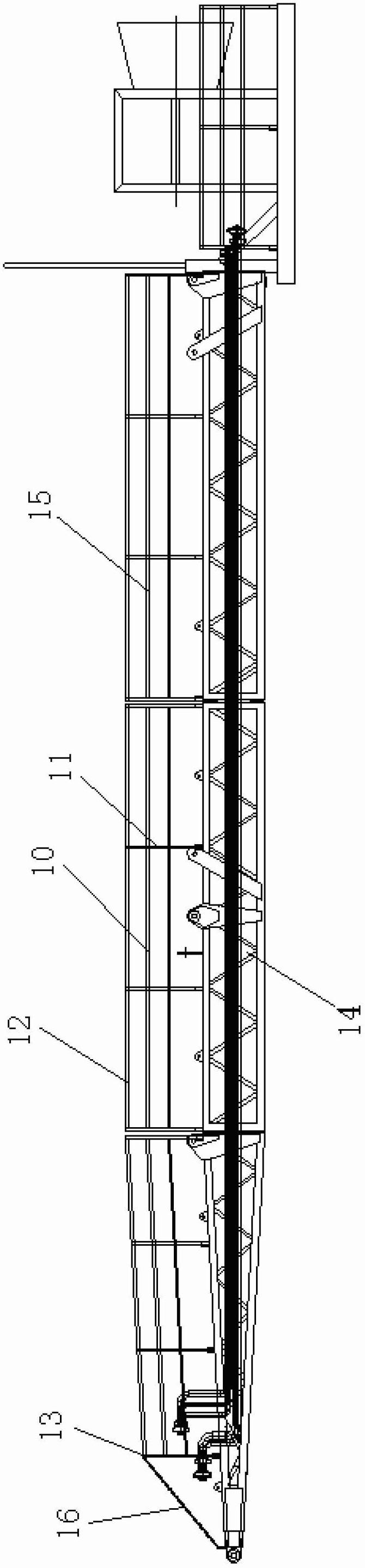
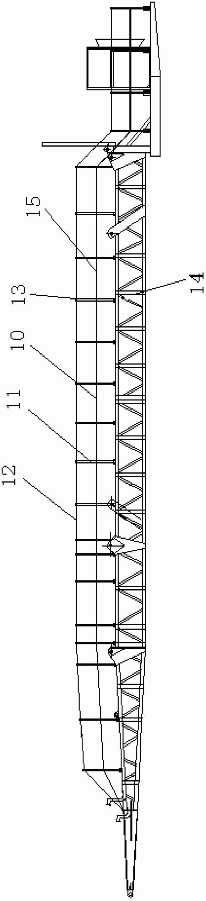
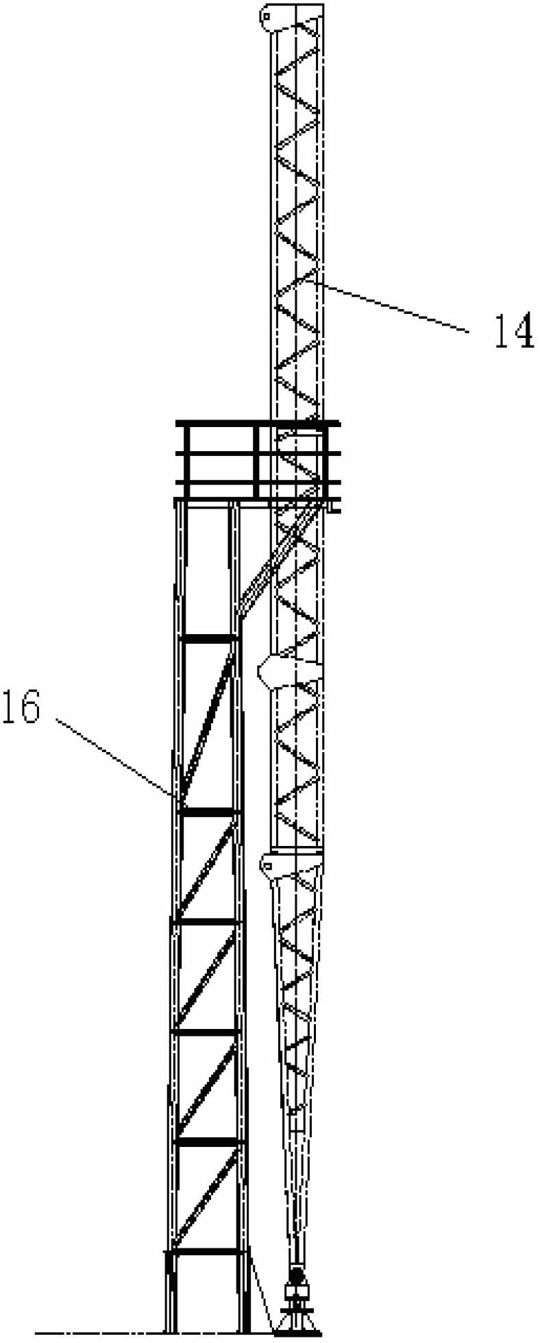
[0022] Such as Figure 5 , Figure 6 As shown, the present invention includes a plurality of cross bars 21 arranged on both sides of the combustion arm 20, and a connection block 22 is respectively arranged at both ends of each cross bar 21, and the connection blocks 22 on two adjacent cross bars 21 pass through a pin 23, and then form an integral beam 24;

[0023] A plurality of connecting plates 25 are arranged at intervals at the bottom of the beam 24, each connecting plate 25 is connected to a vertical rod 26 through a pin shaft 23, and the bottom of each vertical rod 26 is connected to a connecting plate provided on the combustion arm 20 through a pin shaft 23 27. An upper through hole 28 and a lower through hole 29 are provided at intervals in the middle of each vertical pole 26;

[0024] A fixed plate 30 is arranged horizontally at the root ...


PUM


Abstract

The invention relates to a columnar combustion arm guardrail. The columnar combustion arm guardrail comprises a plurality of cross rods arranged on the two sides of a combustion arm; a connecting block is arranged on each of the two ends of each cross rod; the connecting blocks on the adjacent cross rods are connected through a pin shaft to form an integral cross beam; a connecting plate is arranged at the bottom of the cross beam; each connecting plate is connected with an upright rod through a pin shaft; each upright rod is connected with the combustion arm through a pin shaft; an upper through hole and a lower through hole are formed in each upright rod at an interval; a fixing plate is horizontally arranged at the root of the combustion arm; two steel wire ropes and a connecting rod are arranged on the fixing plate; after penetrating through the through holes in each upright rod on the same side, each steel wire rope is fixedly arranged on the upright rod at the other end of the cross beam; steel wire ropes also penetrate through and are fixedly arranged in the lower through holes in the upright rods and the two ends of the steel wire ropes are fixedly arranged on the upright rods at the two ends of the cross beam respectively; each connecting rod is connected with the connecting blocks on the end parts of adjacent cross beams through pin shafts; and the connecting blocks at the other ends of the cross beams are connected to a fixing guardrail arranged on the front part of the combustion arm. The columnar combustion arm guardrail is widely applied to protecting equipment of the petroleum drilling platform combustion arm.

Description

technical field [0001] The invention relates to an oil drilling platform guardrail, in particular to a collapsible column type combustion arm guardrail. Background technique [0002] Such as figure 1 As shown, the guardrail 10 of the column type combustion arm in the prior art generally adopts a hard guardrail, and the vertical bar 11 and the cross bar 12 of the guardrail 10 are welded into one by steel pipes, and the guardrail 10 is fixedly connected to the combustion arm 14 through a pin 13. On the fixed guardrail 15 that front part is connected, the other end is fixedly connected on the connecting rod 16 that combustion arm 14 roots are provided with. Such a guardrail 10 can neither move nor rotate. Such as figure 2 As shown, in the guardrail 10 of the soft combustion arm in the prior art, the upright bar 11 of the guardrail 10 is a steel pipe, the cross bar 12 is a steel wire rope or a chain, and the upright bar 11 and the cross bar 12 are softly connected into one b...

Claims


Application Information

Patent Timeline
Patent Type & Authority Applications(China)
IPC IPC(8): E21B15/00
Inventor 唐明成苏小华
Owner CHINA NAT OFFSHORE OIL CORP
Why Eureka
Try Eureka