
Floating lighthouse type natural-vibration-frequency-adjustable wave-energy directly-driven power generation device

A technology of natural vibration frequency and power generation device, which is applied to ocean energy power generation, engine components, machines/engines, etc., to achieve the effects of simple structure, high practicability, and low production cost

Inactive Publication Date: 2012-09-19
GUANGZHOU INST OF ENERGY CONVERSION - CHINESE ACAD OF SCI
View PDF3 Cites 15 Cited by
  • Summary
  • Abstract
  • Description
  • Claims
  • Application Information

AI Technical Summary

Problems solved by technology

Obviously, different combinations of point absorption technology and subsequent conversion systems can form different power generation methods. Currently, wave power generation systems in demonstration state include underwater floating linear power generation, underwater floating hydraulic power generation, water surface floating hydraulic power generation, and underwater fixed linear power generation. , there is no relevant literature report on the demonstration system using the water surface floating linear power generation method

Method used


Image

  • Floating lighthouse type natural-vibration-frequency-adjustable wave-energy directly-driven power generation device
  • Floating lighthouse type natural-vibration-frequency-adjustable wave-energy directly-driven power generation device
  • Floating lighthouse type natural-vibration-frequency-adjustable wave-energy directly-driven power generation device

Examples


Embodiment

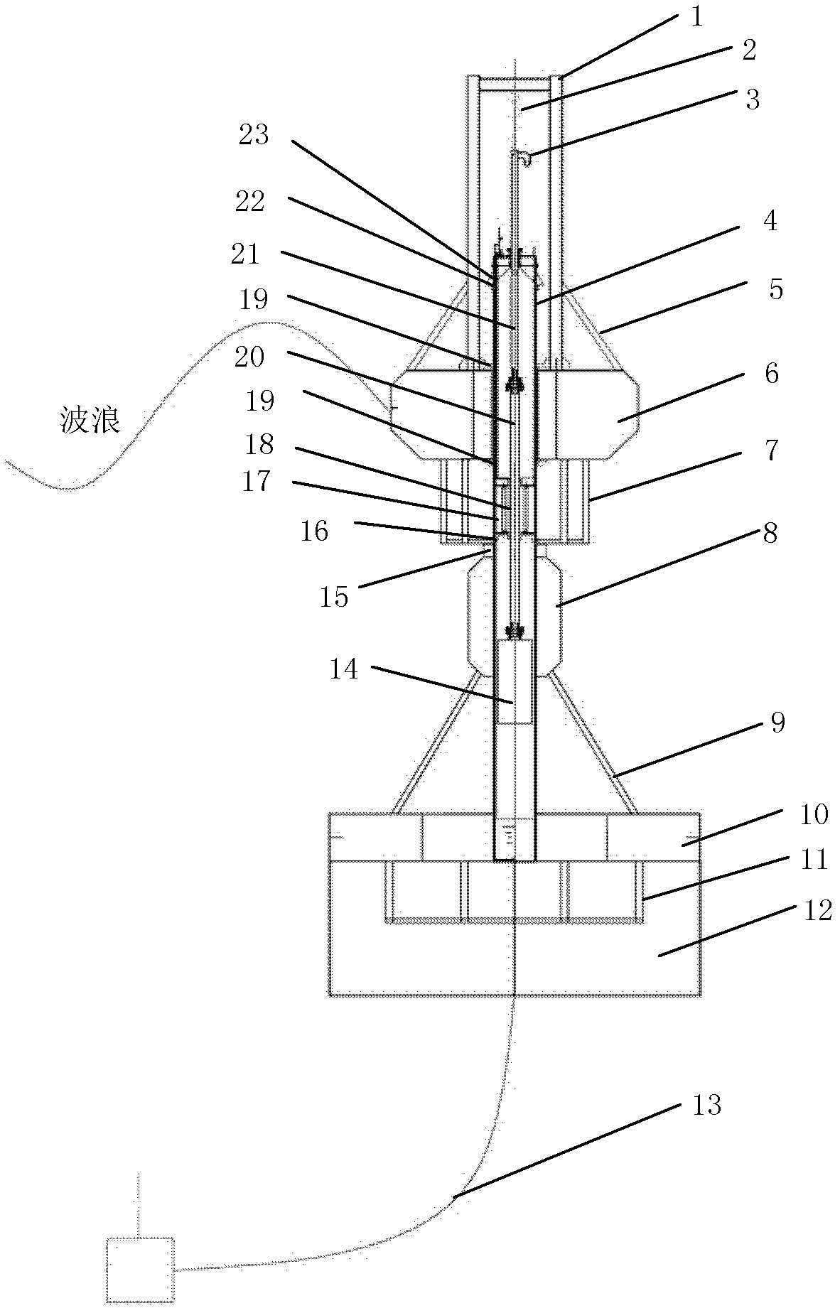
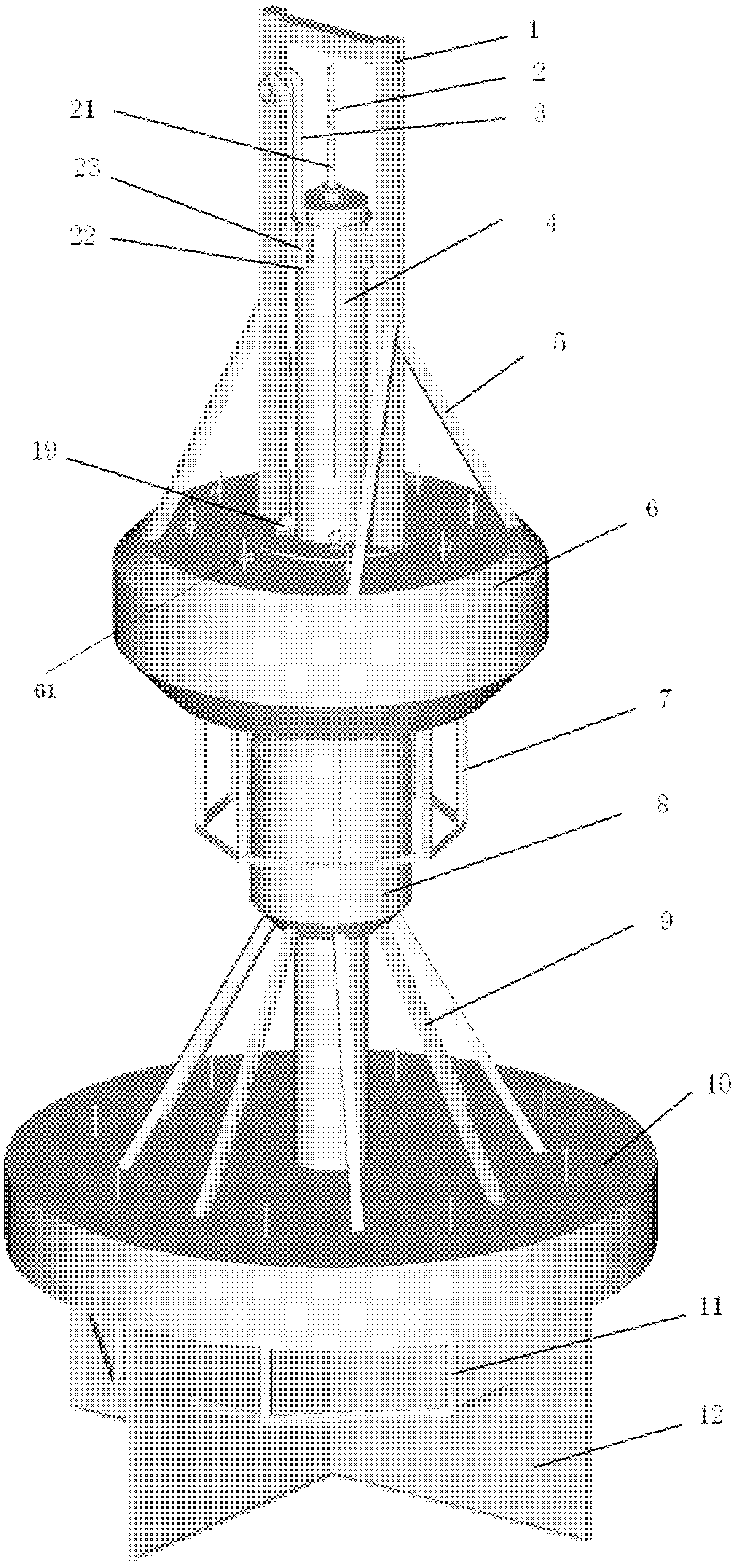
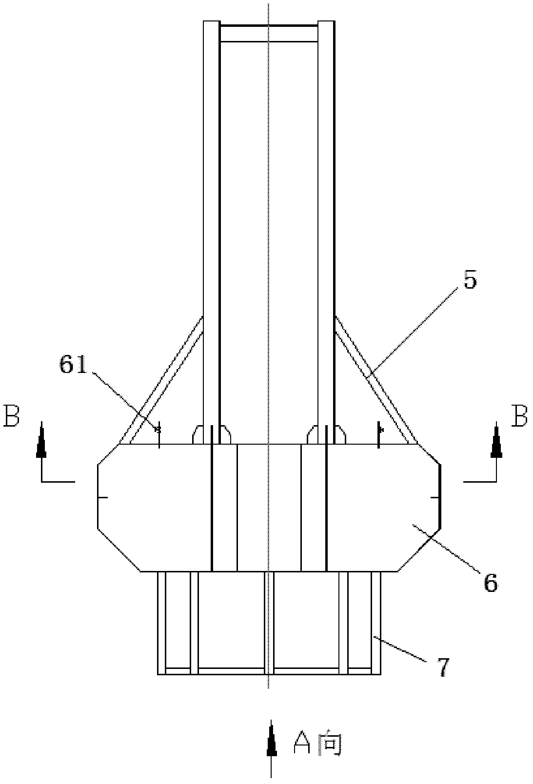
[0033] see Figure 1 to Figure 7 As shown, a floating lighthouse-type wave energy direct drive power generation device with adjustable natural frequency, including: gantry 1, oscillating float 6, flexible connector 2, straight tube 4, two support points at the lower end of gantry 1 are connected On the oscillating float 6, its gantry is connected to the upper end of the flexible connector 2, the lower end of the flexible connector 2 is connected to the upper end of the connecting shaft 21, and the lower end of the connecting shaft 21 is connected to the upper end of the generator rotor 20; the oscillating float 6 is movably sleeved on the straight tube 4 peripheral, a horizontal damping tube 10 is rigidly connected to the lower end of the straight tube 4, and a horizontal damping tube water pipe 11 is connected below the horizontal damping tube 10; the straight tube 4 is equipped with a generator stator 18 and a gravity recovery hammer 14, and the gravity recovery hammer 14 is ...


PUM


Abstract

The invention discloses a floating lighthouse type natural-vibration-frequency-adjustable wave-energy directly-driven power generation device, which is characterized in that two supporting points at the lower end of a portal frame are connected to an oscillating buoy, a portal is connected with the upper end of a flexible connector, the lower end of the flexible connector is connected to the upper end of a connecting shaft, and the lower end of the connecting shaft is connected to the upper end of a generator rotor; the oscillating buoy is movably sleeved on the periphery of a straight cylindrical pipe, the lower end of the straight cylindrical pipe is rigidly connected with a horizontal damping cylinder, and a horizontal damping cylinder water-pipe is connected below the horizontal damping cylinder; a generator stator and a gravity recovery hammer are arranged in the straight cylindrical pipe, and the gravity recovery hammer is connected with the generator rotor; the bottom of the oscillating buoy is provided with an oscillating buoy water-pipe; an additional floating cylinder is sleeved on the straight cylindrical pipe between the oscillating buoy and the horizontal damping cylinder water-pipe; a longitudinal damping plate formed by crossing two plates is connected to the bottom of the horizontal damping cylinder, and the surface of the longitudinal damping plate is vertical to the bottom surface of the horizontal damping cylinder; an anchor chain is connected to the horizontal damping cylinder; and parts (corresponding to the upper and lower upper limit positions of the oscillating buoy) of the straight cylindrical pipe are respectively provided with upper and lower limited blocks of a buffer.

Description

technical field [0001] The invention belongs to the technical field of ocean wave energy development and utilization, and relates to a floating lighthouse-type wave energy direct-drive power generation device with adjustable natural frequency. Background technique [0002] Wave energy is a renewable clean energy with abundant reserves and wide distribution. The development and utilization of wave energy has broad application prospects. [0003] At present, the wave energy conversion technologies proposed in the world are mainly classified according to the capture technology as point absorption (float type), duck type, oscillating water column type, raft type, pendulum type, and surfing wave type, etc., and the midpoint absorption type (float type) technology It has developed rapidly in recent years. This technology uses floats to capture wave energy, and converts wave energy into impeller mechanical energy, hydraulic energy or electric energy through subsequent conversion s...

Claims


Application Information

Patent Timeline
Patent Type & Authority Applications(China)
IPC IPC(8): F03B13/14
CPCY02E10/38Y02E10/30
Inventor 吴必军刁向红王坤林张云秋
Owner GUANGZHOU INST OF ENERGY CONVERSION - CHINESE ACAD OF SCI
Learn More