
Wind turbine

A technology for wind turbines and stators, applied in wind turbines, wind motor combinations, engines, etc., can solve problems such as rotor overheating, and achieve the effects of improving efficiency, reducing losses, and reducing weight

Inactive Publication Date: 2012-09-19
WILIC SARL
View PDF0 Cites 3 Cited by
  • Summary
  • Abstract
  • Description
  • Claims
  • Application Information

AI Technical Summary

Problems solved by technology

[0005] Such wind turbines have proven to be highly efficient and are easy to produce and install, however, it has been found that part of the energy transferred from the blades to the motor is dissipated in so-called electromagnetic losses, especially in the rotor
[0006] Also, the dissipated energy causes the rotor to overheat

Method used


Image

  • Wind turbine
  • Wind turbine
  • Wind turbine

Examples


Embodiment Construction

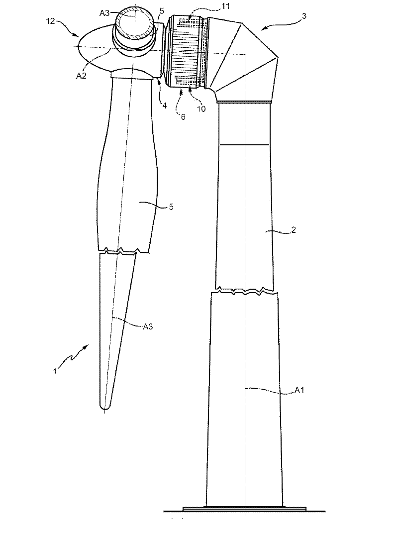
[0019] figure 1 The number 1 in represents as a whole the wind turbines used to generate electrical energy.

[0020] exist figure 1 In the example shown, a wind turbine 1 is of the direct drive, variable angular velocity type and comprises a support structure 2, a nacelle 3, a hub 4, three blades 5 ( figure 1 Only two are shown in ), and the polyphase motor 6. The blades 5 are fitted to the hub 4 , which in turn is fitted to the nacelle 3 , which in turn is fitted to the support structure 2 , which is a structural element supporting the nacelle 3 .

[0021] In a variant of the invention that is not shown, the support structure 2 is a tower, preferably made of ferrous material.

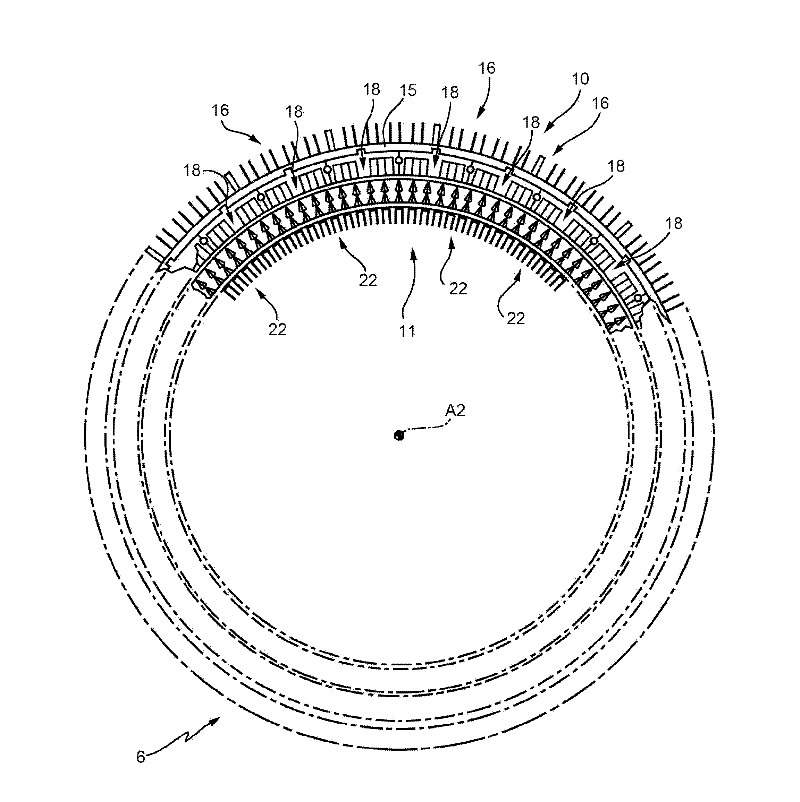
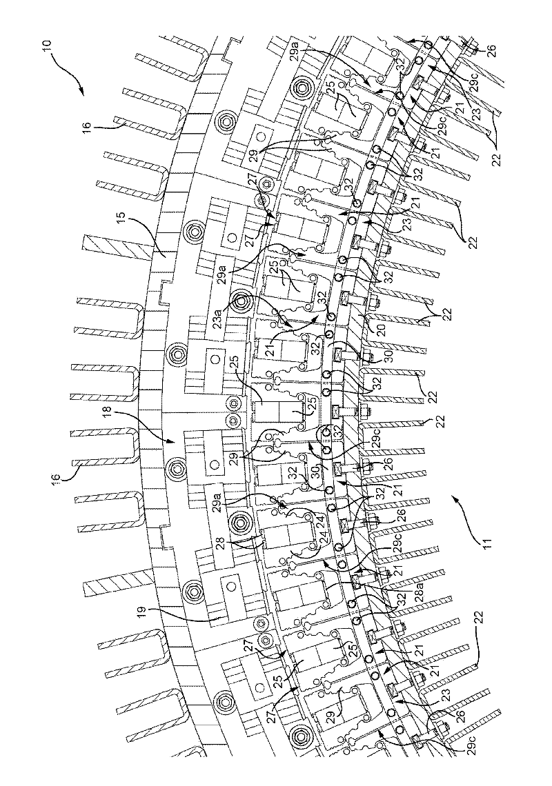
[0022] refer to figure 1 , the nacelle 3 is mounted to rotate about the axis A1 relative to the support structure 2 to position the blades 5 facing the wind; the hub 4 is mounted to rotate about the axis of rotation A2 relative to the nacelle 3; The hub 4 rotates about an axis A3; the electric mac...


PUM


Abstract

A wind turbine has an electric machine (6) in turn having a stator (10), and a rotor (11) which rotates about an axis of rotation (A2) with respect to the stator (10); the rotor (11) has a number of magnetized modules (25), and a number of supports (23) for supporting the magnetized modules (25) and arranged about the axis or rotation (A2); and wherein at least two of the supports (23) are parallel connected electrically.

Description

technical field [0001] The invention relates to a wind turbine for generating electrical energy. [0002] More specifically, the invention relates to a wind turbine comprising an electric machine having a stator and a rotor rotating relative to the stator about an axis of rotation. Background technique [0003] The stator includes a stator cylinder and stator segments arranged around the axis of rotation along the stator cylinder. [0004] The rotor includes a rotor cylinder and rotor segments arranged around the axis of rotation along the rotor cylinder. Each rotor segment includes a frame extending parallel to the axis of rotation and a magnetization module arranged within the frame parallel to the axis of rotation. The rotor segment is fitted to the rotor cylinder and the stator segment is fitted to the stator cylinder. The rotor cylinder is connected to the stator cylinder by at least one bearing, and to a hub and a plurality of blades arranged around the hub. [000...

Claims


Application Information

Patent Timeline
Patent Type & Authority Applications(China)
IPC IPC(8): F03D9/00F03D1/00H02K1/28
CPCH02K7/1838Y02E10/725H02K1/2786H02K11/0089F05B2220/7066F03D9/002H02K1/2773H02K1/223F03D9/25H02K1/28H02K3/42H02K7/183H02K11/01H02K1/2791H02K11/40F03D15/20Y02E10/72
Inventor 马特奥·卡萨扎奥托·帕布斯特亚历山德罗·法索洛
Owner WILIC SARL
Learn More