A microfluidic fuel cell with a separator membrane
A fuel cell and separation membrane technology, applied in fuel cells, circuits, electrical components, etc., can solve problems such as fuel or oxidant penetration, battery performance impact, battery performance degradation, etc., to eliminate disturbances, improve battery performance, and reduce parasitic The effect of current
- Summary
- Abstract
- Description
- Claims
- Application Information
AI Technical Summary
Problems solved by technology
Method used
Image
Examples
Embodiment 1
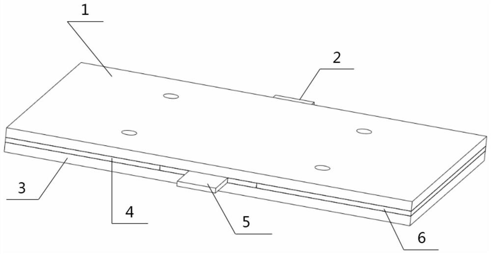
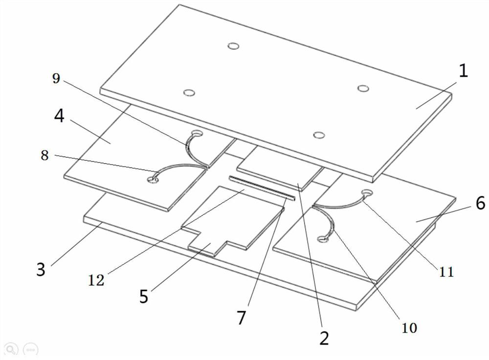
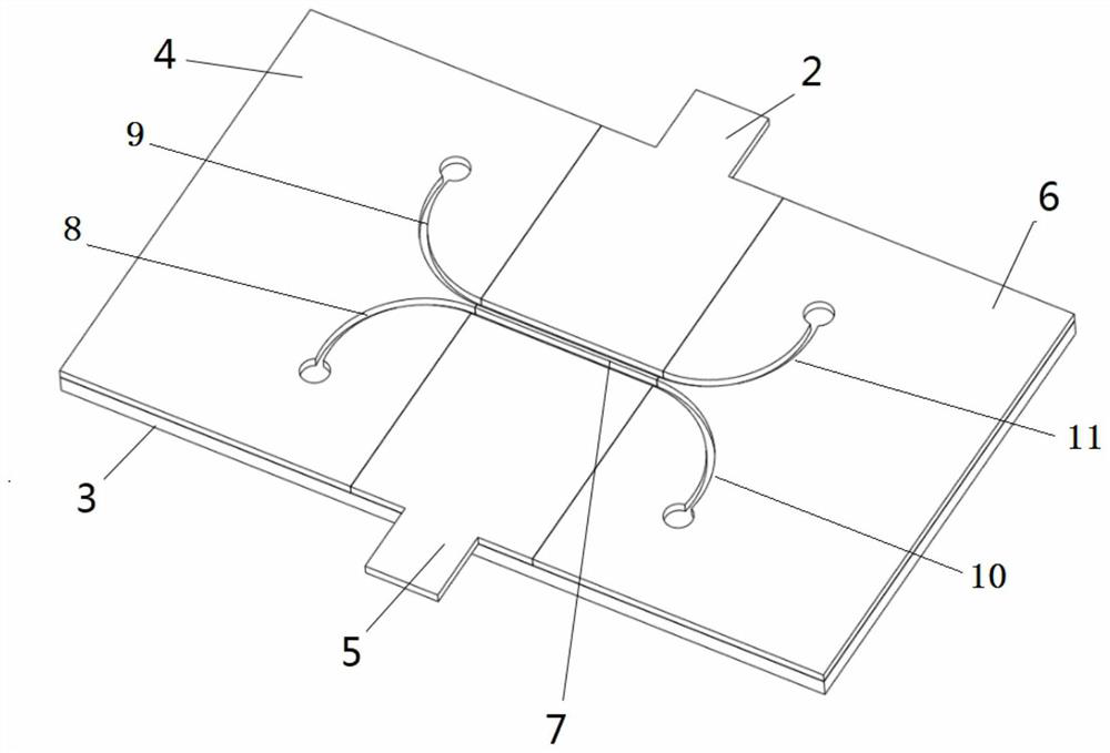
[0019] Example 1, see Figure 1 to Figure 3 , a microfluidic fuel cell with a separator, comprising an upper cover plate 1, a lower cover plate 3, a cathode 5, an anode 2, an inlet plate 4 and an outlet plate 6; it is characterized in that: the cathode 5, the anode 2, the inlet Both the plate 4 and the outlet plate 6 are placed on the lower cover plate 3, located below the upper cover plate 1; the anode 2 and the cathode 5 are arranged opposite to each other on the left and right, and there is a gap 12 between the cathode 5 and the anode 2, and the gap 12 serves as A main channel for the solution to flow; the main channel is provided with a separation membrane 7, and the separation membrane 7 divides the main channel into left and right flow channels; the separation membrane 7 is a porous filter paper with hydrophilicity; The inlet plate 4 and the outlet plate 6 are respectively arranged on the front and rear sides of the main channel; the inlet plate 4 is provided with two in...
Embodiment 2
[0025] Example 2 is different from Example 1 in that: the separation membrane 7 is a nylon membrane prepared by an in-situ chemical reaction synthesis method.
[0026] Specifically: the solution obtained by dissolving the hexamethylenediamine aqueous solution and the adipoyl chloride solution in the organic solvent is injected into the two inlet channels 8 and 9 respectively at a flow rate of 60-100 μL / min, enters the main channel, and forms in the main channel At the water-oil interface, hexamethylenediamine and adipoyl chloride molecules in the solution diffuse to the water-oil interface to undergo polycondensation reaction to produce polyamide. After continuous reaction, a layer of porous nylon membrane is formed in the main channel. Finally, ethanol is injected into the inlet channel first. Rinse the nylon membrane in the process, inject a deionized aqueous solution into the inlet channel to rinse the nylon membrane, and then inject nitrogen gas into the inlet channel to pu...
Embodiment 3
[0029] Embodiment 3: the microfluidic fuel cell with separation membrane that operation embodiment 1 makes, and described anode 2 oxidizes fuel and produces electron and produces CO 2gas bubbles, the cathode 5 reduces persulfate ions in the oxidizer and combines electrons to generate sulfate ions. Catalysts such as Pd on the anode catalytic layer perform electrocatalytic oxidation of fuels such as formic acid to generate carbon dioxide, electrons and hydrogen ions. The electrons reach the cathode 5 through the load through the external circuit to generate electric energy. After a period of reaction, the carbon dioxide produced at the anode is released to form CO 2 The air bubbles are restricted on the anode side by the separator, and finally the air bubbles are discharged along the flow channel.
[0030] see Figure 4 , Figure 4 It is the power density curve figure of the microfluidic fuel cell of embodiment 1 and the microfluidic fuel cell without filter paper separating...
PUM
 Abstract
Description
Claims
Application Information
 - R&D
- Intellectual Property
- Life Sciences
- Materials
- Tech Scout
- Unparalleled Data Quality
- Higher Quality Content
- 60% Fewer Hallucinations
Browse by: Latest US Patents, China's latest patents, Technical Efficacy Thesaurus, Application Domain, Technology Topic, Popular Technical Reports.
© 2025 PatSnap. All rights reserved.Legal|Privacy policy|Modern Slavery Act Transparency Statement|Sitemap|About US| Contact US: help@patsnap.com


