Magnetic plasma propeller

A magnetic plasma and thruster technology, applied in the direction of using plasma, thrust reverser, machine/engine, etc., can solve the problems that have not been reported in the literature, MPDT research is basically zero, etc., and achieve the convenience of parts replacement and adjustment Effect

Inactive Publication Date: 2012-09-19
BEIHANG UNIV
View PDF4 Cites 28 Cited by
  • Summary
  • Abstract
  • Description
  • Claims
  • Application Information

AI Technical Summary

Problems solved by technology

[0004] Domestic research on plasma behavior in a magnetic field is mostly based on magnetic confinement technology, such as the tokamak device. Meticulous research work, but the research on MPDT is basically zero, and no relevant literature reports have been seen

Method used


Image

  • Magnetic plasma propeller
  • Magnetic plasma propeller

Examples


Embodiment Construction

[0030] The present invention will be further described in detail below in conjunction with the accompanying drawings and embodiments.

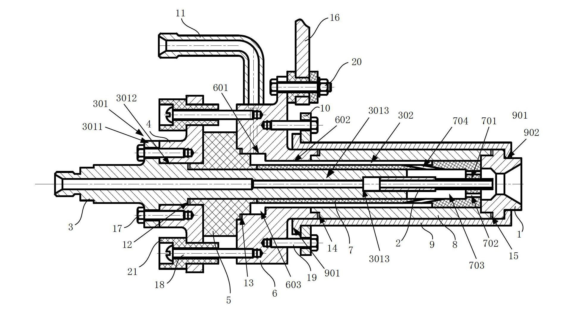
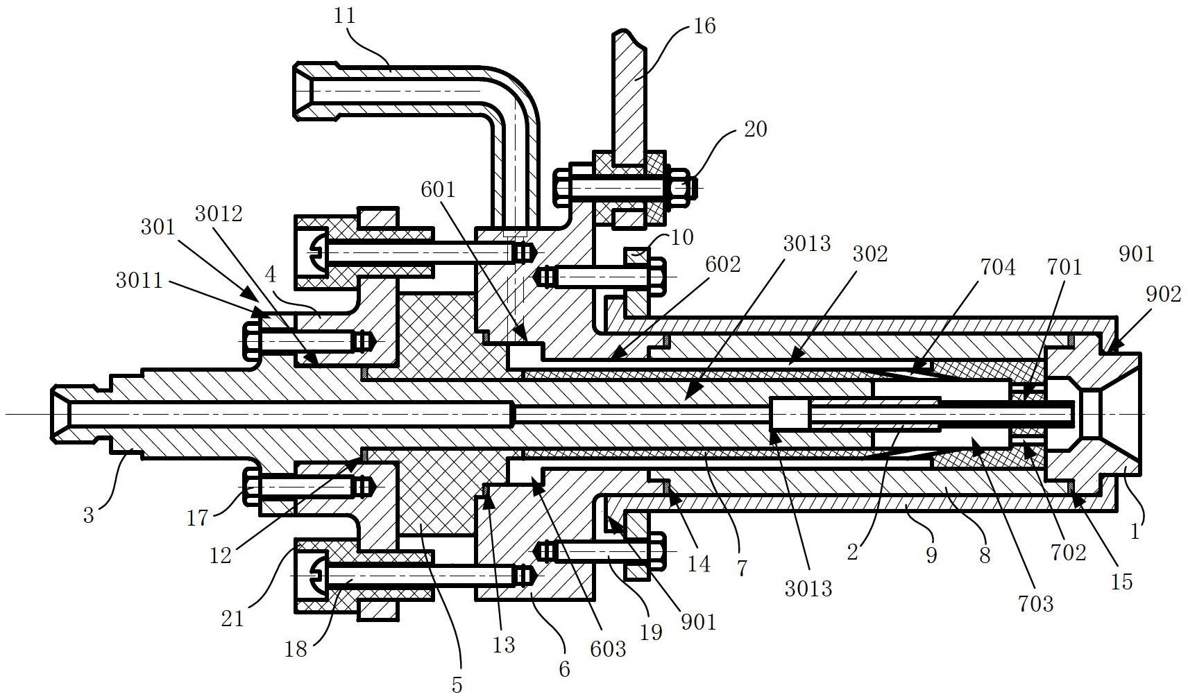
[0031] The magnetic plasma thruster of the present invention includes an anode 1, a cathode 2, a cathode mounting part 3, an end cover 4, a support body 5, a middle connecting part 6, an insulating cylinder 7, an anode bushing 8, an anode casing 9, and an anode retaining ring 10 and the intake duct 11, such as figure 1 shown.

[0032] Wherein, the cathode mounting part 3 is a straight circular tube structure, which is used as a support for the components in the entire thruster; the outer wall of the rear part of the cathode mounting part 3 is circumferentially designed with an annular flange A301. The end cover 4, the support body 5 and the insulating cylinder 7 are coaxially sleeved on the cathode mounting part 3, the rear end surface of the end cover 4 is attached to the front surface of the annular flange A301, and is fixedly connected to ...


PUM


Abstract

The invention discloses a magnetic plasma propeller. An end cover, a supporting body and an insulation cylinder are sleeved on a cathode mounting piece from back to front; and a discharging cavity is formed between the front end face of the insulation cylinder and the front end face of the cathode mounting piece. A middle connection piece and an anode liner are sleeved on the insulation cylinder from back to front; an air inlet pipeline is communicated on the middle connection piece; air inlet channels are formed among the middle connection piece, the anode liner and the cathode mounting piece; air inlets are formed in the front end face of the insulation cylinder; and an anode is positioned with the insulation cylinder through an anode shell. A cathode is located inside the cathode mounting piece; and the front end of the cathode penetrates out of the front end face of the insulation cylinder, and is located inside the anode. Propellant is supplied by two paths; one path reaches to a position of the anode by passing through the air inlet pipeline, an air inlet cavity, the air inlet channel, a gas port, the discharging cavity and the air inlets in sequence; the other path reaches to the position of the anode by passing through the inside of the cathode mounting piece and the inside of the cathode in sequence; and the propellant in the two paths is mixed and then is subjected to discharging ionization between the cathode and the anode. The invention provides an electric propeller which uses argon as the propellant and supplies a milli-Newton level trust within a power range of 30-50 kW.

Description

technical field [0001] The invention relates to the technical field of space electromagnetic electric thrusters, in particular to a magnetoplasma thruster. Background technique [0002] The magnetoplasma thruster (MPDT), which once existed in science fiction, is considered to be one of the best candidate propulsion schemes for exploring the mysteries of deep space because of its easy combination with high nuclear power and miniaturization. It mainly uses the current discharge between the electrodes to ionize the incoming gas working fluid to generate plasma, and the plasma is ejected at high speed under the action of electromagnetic field and aerodynamic acceleration to generate thrust. In recent years, with the proposal of high-power space propulsion and the demand for space missions, MPDTs that can be connected to high-power space power sources have once again become an international research hotspot. Magnetoplasma engines have high exhaust velocity, high thrust, high eff...

Claims


Application Information

Patent Timeline
Patent Type & Authority Applications(China)
IPC IPC(8): F03H1/00
Inventor 汤海滨程蛟刘畅杨渊李明新李敏
Owner BEIHANG UNIV
Why Eureka
Try Eureka