
Noise eliminating device for reducing exhaust noise of internal combustion engine

A technology for noise reduction devices and internal combustion engines, which is applied in the direction of exhaust devices, noise reduction devices, mechanical equipment, etc. It can solve the problems of easy injury, inconvenient installation, and large exhaust muffler, so as to prevent excessive temperature, facilitate installation, small size effect

Inactive Publication Date: 2018-12-11
全椒县全动机械有限公司
View PDF9 Cites 4 Cited by
  • Summary
  • Abstract
  • Description
  • Claims
  • Application Information

AI Technical Summary

Problems solved by technology

Existing exhaust mufflers need to be equipped with a long noise reduction channel for noise reduction, which consumes the sound energy of the exhaust and avoids noise. Due to the long noise reduction channel, the existing exhaust mufflers are usually large in size and inconvenient to install, and There is no gas cooling function, because the temperature of the gas discharged from the internal combustion engine is too high, it is easy to hurt people

Method used


Image

  • Noise eliminating device for reducing exhaust noise of internal combustion engine
  • Noise eliminating device for reducing exhaust noise of internal combustion engine
  • Noise eliminating device for reducing exhaust noise of internal combustion engine

Examples


Embodiment Construction

[0015] The following will clearly and completely describe the technical solutions in the embodiments of the present invention with reference to the accompanying drawings in the embodiments of the present invention. Obviously, the described embodiments are only some, not all, embodiments of the present invention. Based on the embodiments of the present invention, all other embodiments obtained by persons of ordinary skill in the art without making creative efforts belong to the protection scope of the present invention.

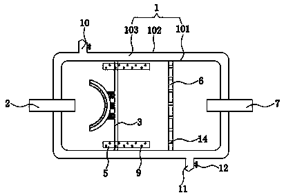
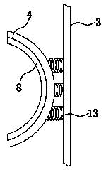
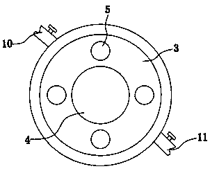
[0016] see Figure 1-3 , the present invention provides a technical solution: a noise reduction device for reducing exhaust noise of an internal combustion engine, comprising a casing 1, the casing 1 includes an inner casing 101 and an outer casing 102, and the inner casing 101 and the outer casing A cavity 103 is formed between 102, the left side of the housing 1 is provided with an air intake pipe 2, and the air intake pipe 2 extends into the inner cavity of...


PUM


Abstract

The invention discloses a noise eliminating device for reducing the exhaust noise of an internal combustion engine. The noise eliminating device comprises a shell, wherein the shell comprises an innershell and an outer shell, a cavity is formed between the inner shell and the outer shell, an air inlet pipe is arranged on the left side of the shell, the air inlet pipe extends into the inner cavityof the shell, a first baffle is arranged in the inner cavity of the shell, a buffer groove is formed in the middle of the left side of the first baffle plate, the buffer groove and the air inlet pipeare located on the same horizontal plane, and noise eliminating pipes are arranged on the periphery of the buffer groove. Through the arrangement of the buffer groove, the airflow can play a role inbuffering when coming out of the air inlet pipe, and the air flow can circularly flow on the left side of the first baffle to reduce the noise; sound absorbing cotton is arranged on the inner surfaceof the buffer groove, so that when the air flow is transmitted to the buffer groove, the effect of absorbing noise is achieved; the noise eliminating pipes are arranged, so that air flow is transmitted to the right side of the first baffle from the left side of the first baffle; and first noise eliminating holes are formed, so that the energy of the air flow in the noise eliminating pipes is prevented from being attenuated, and the effect of noise eliminating is achieved.

Description

technical field [0001] The invention relates to the technical field of internal combustion engines, in particular to a noise reduction device for reducing exhaust noise of internal combustion engines. Background technique [0002] During the working process of the internal combustion engine, a large amount of exhaust gas will be burned. The main component of these exhaust gases is carbon dioxide. Larger noises are generated. In order to avoid pollution caused by these noises, it is necessary to reduce the decibel of the exhaust sound. Existing exhaust mufflers need to be equipped with a long noise reduction channel for noise reduction, which consumes the sound energy of the exhaust and avoids noise. Due to the long noise reduction channel, the existing exhaust mufflers are usually large in size and inconvenient to install, and Without the cooling function of the gas, the temperature of the gas discharged from the internal combustion engine is too high, which is easy to hurt...

Claims


Application Information

Patent Timeline
Patent Type & Authority Applications(China)
IPC IPC(8): F01N13/00F01N1/08F01N3/04
CPCF01N1/08F01N1/082F01N1/084F01N3/04F01N13/007
Inventor 尤建国
Owner 全椒县全动机械有限公司
Learn More