Primary-secondary ejector

A technology of injector and parent-child, which is applied in the field of dual-fluid mixed-flow components, can solve the problems of complex and special structures, and the inapplicability of large-flow ejectors, etc., and achieve good working-hour performance, reduced axial size and weight, Fluid Powerful Effects

Inactive Publication Date: 2012-09-19
韩铁夫
View PDF8 Cites 4 Cited by
  • Summary
  • Abstract
  • Description
  • Claims
  • Application Information

AI Technical Summary

Problems solved by technology

Although multiple small jets can be connected in parallel to form a large jet pump, their function is mainly for underground oil production pumping, and

Method used


Image

  • Primary-secondary ejector
  • Primary-secondary ejector
  • Primary-secondary ejector

Examples


Example Embodiment

[0033] One, embodiment one

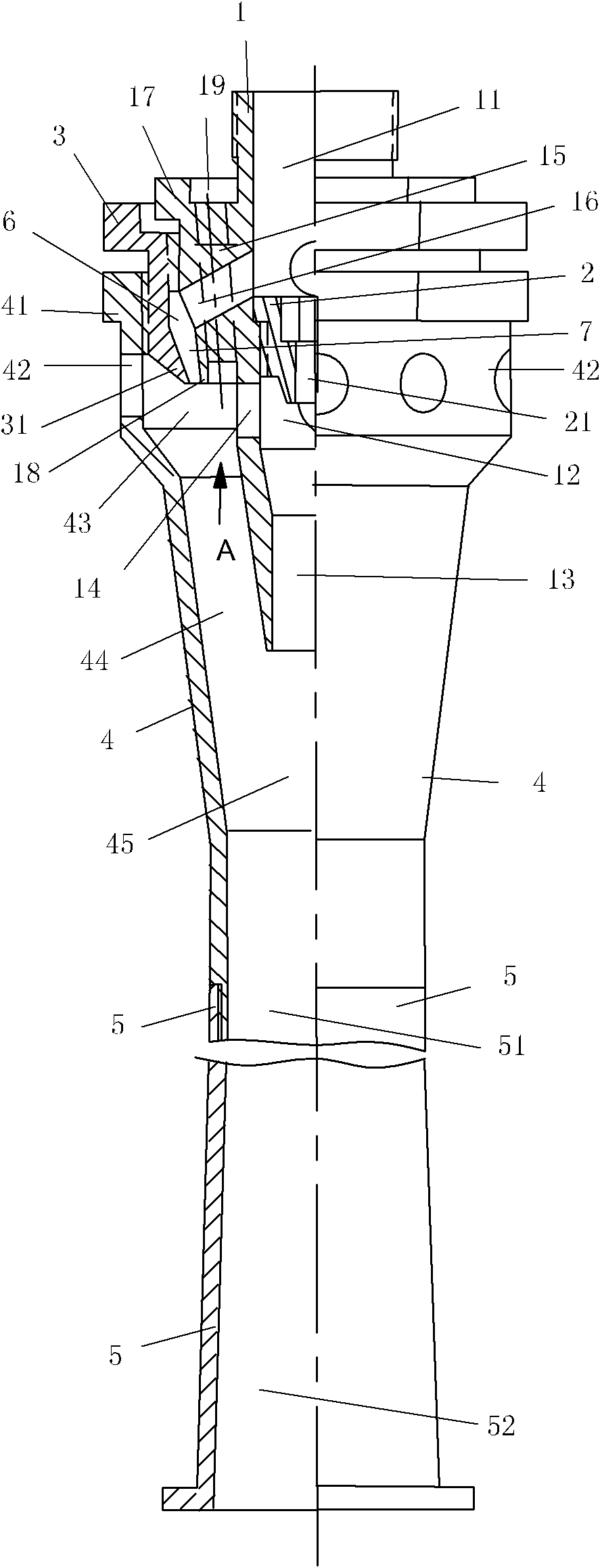
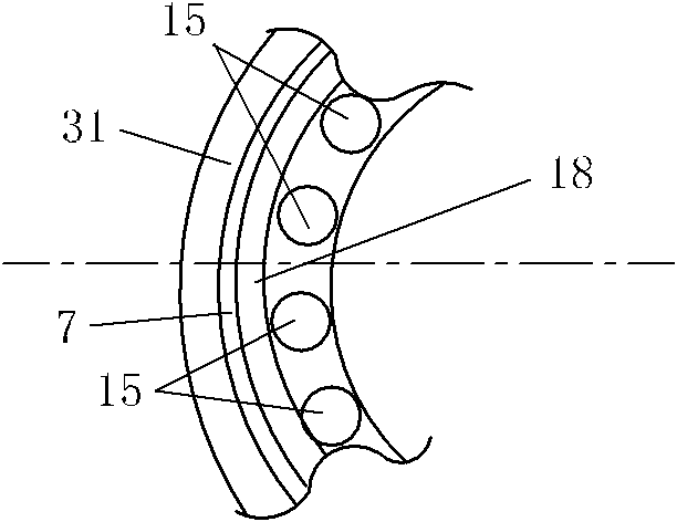
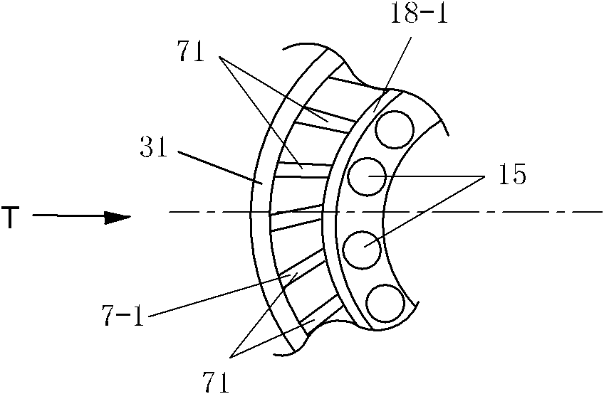
[0034] The structure of the first embodiment of the composite ejector of the present invention, such as figure 1 As shown, figure 1 The top in the middle is the actual front, and the bottom is the actual rear. The composite ejector is composed of a short inner tube 1, a central nozzle 2, a connecting sleeve 3, a thick and long outer tube 4, and an annular nozzle 7. The inner tube 1 and the central nozzle 2 form a central ejector, and the inner tube 1, the outer tube 4, the connecting sleeve 3 and the annular nozzle 7 form an annular ejector. The input end of the central ejector is coaxially fixed in the entrance of the enlarged diameter section 41 of the input end of the annular ejector, and the rear section of the central ejector is coaxially suspended in the annular ejector. The middle and rear sections of the outer tube 4 that are longer in the axial direction than the outlet end of the inner tube 1 constitute a total mixing output pipe. The inlet...

Example Embodiment

[0046] Two, embodiment two

[0047] The structure of the second embodiment of the parent-child ejector of the present invention, such as Figure 5 Shown. Figure 5 The top in the middle is the actual front, and the bottom is the actual rear. The composite ejector is composed of a short and small inner tube 10, a central nozzle 20, a connecting sleeve 30, and a thick and long outer tube 40. The inner tube 10 and the central nozzle 20 constitute a central ejector. The inner tube 10, the connecting sleeve 30, and the outer tube 40 form an annular ejector. The central ejector is coaxially arranged in the annular ejector, and the central ejector and the outlet of the annular ejector jointly communicate with the total mixing chamber 450 and the total mixing pipe 460.

[0048] The front part of the inner tube 10 is a large-diameter straight circular central hole, and the middle part is an enlarged diameter hole section composed of a straight circular hole section with the largest diamet...

Example Embodiment

[0062] Three, embodiment three

[0063] See Figure 8 The structure of this embodiment is basically the same as that of the second embodiment. Figure 8 The top in the middle is the actual front, and the bottom is the actual rear. The parent-child ejector is composed of a short inner tube 100, a central nozzle 200, a connecting sleeve 300, and a thick and long outer tube 400. The inner tube 100 and the central nozzle 200 form a central ejector, and the inner tube 100, the outer tube 400, and the connecting sleeve 300 form an annular ejector. The input end of the central ejector is coaxially fixed in the entrance of the enlarged diameter section of the input end of the annular ejector, and the rear section of the central ejector is coaxially suspended in the annular ejector. The middle and rear sections of the outer tube 400 axially longer than the outlet end of the inner tube 100 constitute the total mixing output tube. The inlet section of the total mixing output tube is the ...


PUM


Abstract

The invention provides a primary-secondary ejector and relates to a fluid mixing element for fluids. A central ejector of the primary-secondary ejector is coaxially arranged in an annular ejector; outlets of the central ejector and the annular ejector are communicated with a main mixing chamber and a main mixing tube; one part of a main fluid is ejected from the top of the central ejector to an inlet of a central mixing tube through a central nozzle, is utilized to inject a secondary fluid entering into a central mixing chamber from an inlet in a side position on the upper part of the annular ejector into the central mixing tube and is mixed with the secondary fluid; the other part of the main fluid is ejected from the top of the annular ejector to the inlet of an annular mixing tube through an annular nozzle, is utilized to inject the secondary fluid entering into an annular mixing chamber from the inlet in the side position on the upper part of the annular ejector into the annular mixing tube and is mixed with the secondary fluid; and an ejected fluid at the outlet of the central mixing tube in the main mixing chamber is utilized to inject the surrounding ejected fluid at the outlet of the annular mixing tube into the main mixing tube and is mixed for the third time, thereby finishing the mixed fluid conveying in a way that the high-pressure main fluid pumps the low-pressure secondary fluid. The primary-secondary ejector is short in axial size and high in pumping and ejecting efficiency.

Description

technical field [0001] The invention relates to a two-fluid mixed flow element, in particular to a female-female ejector. Background technique [0002] The dual-fluid injector is a device that injects a low-pressure (or no-pressure) secondary fluid with a relatively high-pressure primary fluid, and completes the suction of the secondary fluid by the primary fluid for mixed-mixing, equal-pressure, and mixed-flow delivery. It is simple and reliable, and is used in many kinds of fluid equipment. A typical existing Venturi ejector consists of a primary fluid inlet, a nozzle, a secondary fluid inlet, a mixing chamber, a throat or a mixing diffuser. The secondary fluid passed into the mixing chamber is sucked into the mixing tube by the jet of the primary fluid nozzle, and the primary and secondary fluid is output from the mixing diffuser tube after being mixed and equalized. This ejector has a central nozzle and a single elongated mixing diffuser tube. Existing single-pipe eje...

Claims


Application Information

Patent Timeline
IPC IPC(8): F04F5/00
Inventor 韩铁夫
Owner 韩铁夫
Why Eureka
Try Eureka