Guardrail rotary joint assembly and guardrail

A technology of rotating joints and rotating connections, which is applied in the connection of poles, connecting components, mechanical equipment, etc., can solve the problems of low safety and service life of guardrails, low overall strength of guardrails, and inability to close and close the guardrails, so as to improve waterproofness. The effect of sealing performance and overall stability, convenient and quick installation, and improving connection stability

Inactive Publication Date: 2012-09-19
HUNAN GOLDWELL NEW MATERIALS TECH CO LTD
View PDF5 Cites 4 Cited by
  • Summary
  • Abstract
  • Description
  • Claims
  • Application Information

AI Technical Summary

Problems solved by technology

The fixed part and the movable part of this kind of guardrail are both separate integral structures, wherein the fixed part is connected by fixed beams and fixed tubes to form a whole with a frame, and the movable part is connected by a movable beam and a movable tube to form a whole with a frame. As a whole, the frames of the two are connected by hinges, which leads to the fact that two frames must be arranged side by side at the junction of the fixed part and the movable part of the guardrail, resulting in an increase in the amount of consumables for the frame, which increases the production cost and increases the difficulty of production; the movable part After rotating and opening, only the hinge is connected to the fixed part and bears the load. The shear force of the movable part's own weight on the hinge is likely to cause deformation and damage to the hinge, resulting in problems such as the guardrail cannot be closed or closed in place.
In addition, the hinge is used to connect the fixed part and the movable part, which is inconvenient to install, the overall strength of the guardrail after installation is not high, and the safety and service life of the guardrail are also low

Method used


Image

  • Guardrail rotary joint assembly and guardrail
  • Guardrail rotary joint assembly and guardrail
  • Guardrail rotary joint assembly and guardrail

Examples


Embodiment Construction

[0027] The present invention will be further described in detail below in conjunction with the accompanying drawings and specific embodiments.

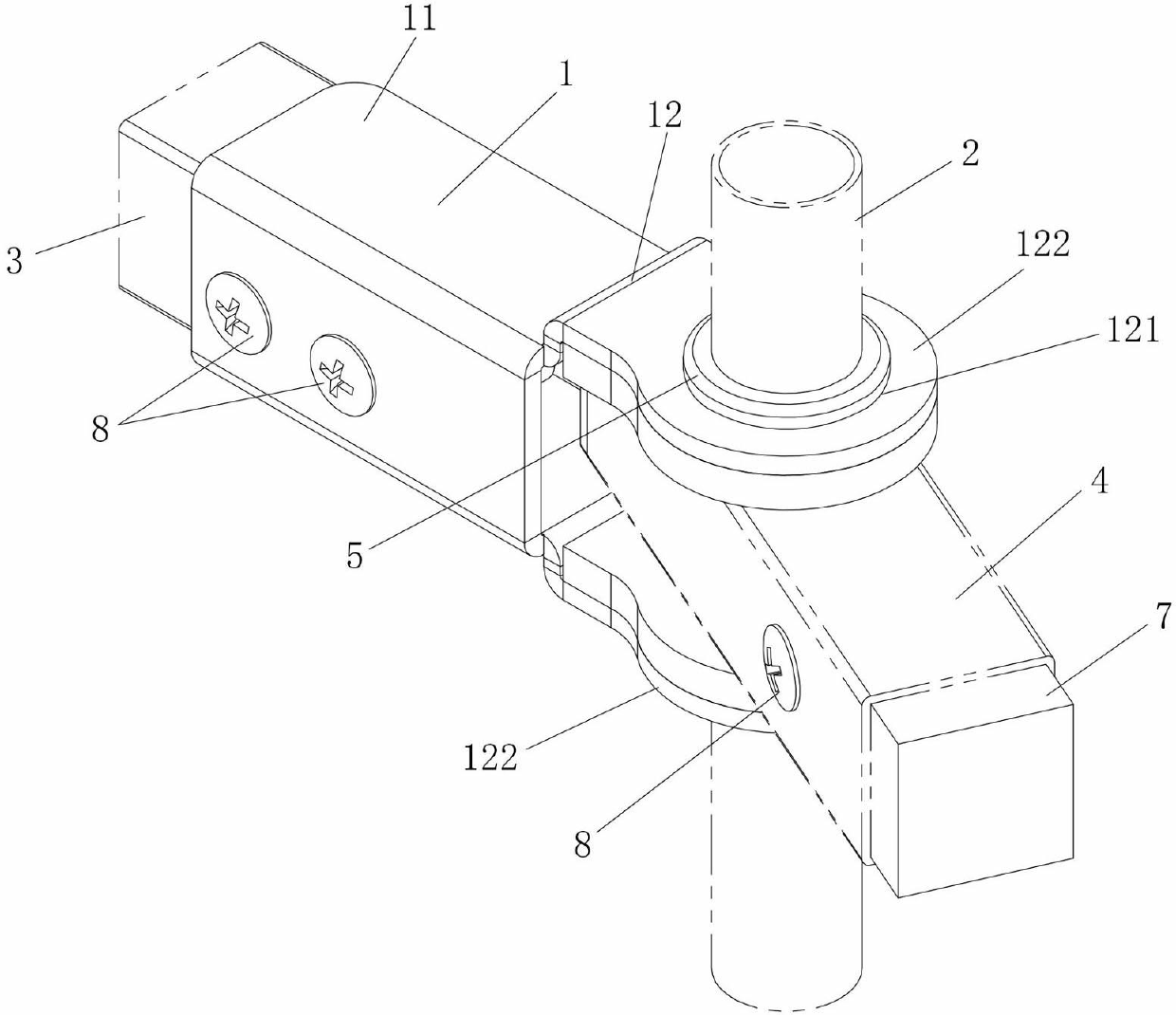
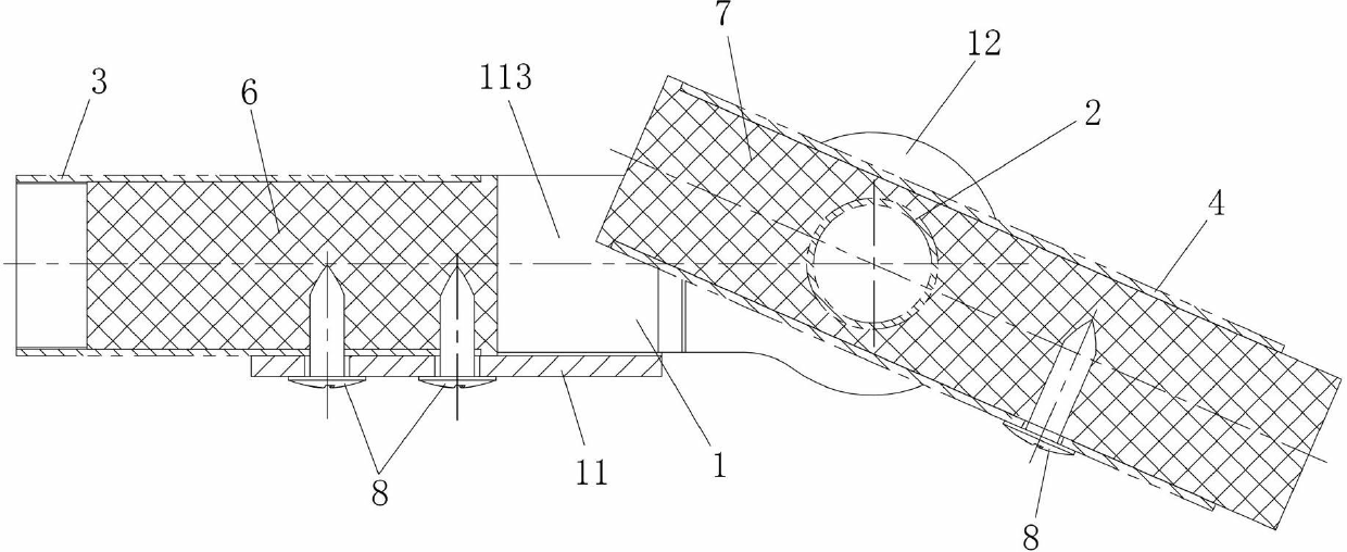
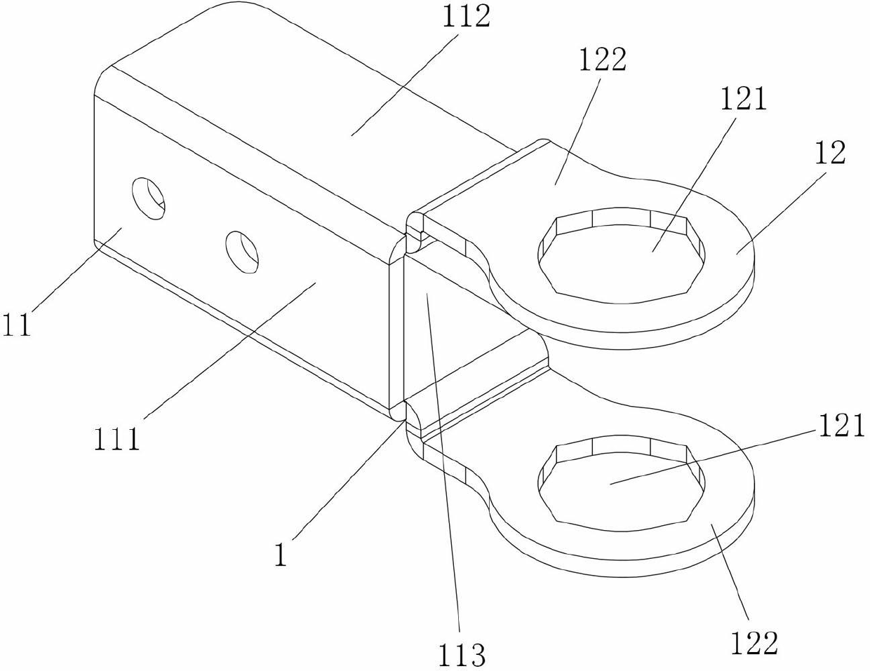
[0028] Figure 1 to Figure 6 Shown is an embodiment of the swivel joint assembly used for the guardrail of the present invention, including the joint body 1, the joint body 1 is provided with a fixed pipe connection part 12 and a movable beam connection part 11, and the movable beam connection part 11 is fastened Part 8 is tightly connected with the movable beam 3 in the guardrail, and the fixed pipe connecting part 12 is provided with a rotating connection hole 121, which is a through hole, and the joint body 1 is sleeved in the fixed part of the guardrail near the movable part through the rotating connecting hole 121. outside the tube 2, and rotate with the fixed tube 2 as the central axis. When assembling the movable part and the fixed part of the guardrail, a plurality of rotating joint assemblies in the present invention can be u...


PUM


Abstract

The invention discloses a guardrail rotary joint assembly and a guardrail. The rotary joint assembly includes a joint body rotating through taking a fixed pipe near a movable part in the guardrail as a center shaft; the joint body is provided with a fixed pipe connecting part used for being connected with a fixed pipe, and a movable beam connecting part used for being connected with a movable beam in the guardrail. The guardrail includes the movable beam at the movable part as well as the fixed pipe at the fixed part; and the movable beam is connected with the fixed pipe near to the movable part through the guardrail rotary joint assembly. The guardrail rotary joint assembly and the guardrail both provided by the invention have the advantages of simple structure, low cost, convenience and fastness in installation, high bonding strength, and long service life.

Description

technical field [0001] The invention relates to assembly fittings connected by pipes, in particular to a rotary joint component and a guardrail used for a guardrail. Background technique [0002] Guardrail is a common pipe connection product. It is generally composed of beams and cylindrical vertical pipes. Among them, multiple horizontal beams are arranged at intervals up and down, and multiple vertical pipes are inserted in the beams at intervals along the vertical direction, and are connected with the beams. Connect to form a whole guardrail. [0003] In practical applications, guardrails usually need to have the function of rotating and opening. For example, there is a guardrail composed of a fixed part and a movable part. The fixed part is installed and fixed, and the movable part is connected to the fixed part through a hinge. It can be rotated relative to the fixed part to realize the function of opening or closing. The fixed part and the movable part of this kind o...

Claims


Application Information

Patent Timeline
Patent Type & Authority Applications(China)
IPC IPC(8): F16B7/00
Inventor 谢斌泉许又配
Owner HUNAN GOLDWELL NEW MATERIALS TECH CO LTD
Why Eureka
Try Eureka