Eureka AIR delivers breakthrough ideas for toughest innovation challenges, trusted by R&D personnel around the world.

Novel oil leakage preventing sealing structure for automobile hydraulic power steering gear shaft end

A technology of hydraulic power and steering gear, which is applied to the sealing of the engine, fluid steering mechanism, engine components, etc., can solve the leakage of high pressure oil in the power steering gear assembly, affecting the service life and reliability of the car, and the appearance is not clean, etc. problems, to achieve the effect of eliminating oil leakage, improving quality and reducing costs

Inactive Publication Date: 2012-09-19
DALIAN RUIGU SCI & TECH
View PDF5 Cites 0 Cited by
  • Summary
  • Abstract
  • Description
  • Claims
  • Application Information

AI Technical Summary

Problems solved by technology

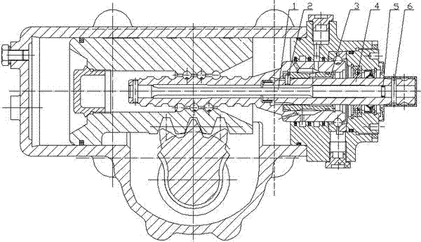
The shaft end oil leakage prevention structure of the power steering gear before improvement (see figure 1 ) is to design the positioning pin for fixing the torsion bar and the input shaft on the input shaft exposed outside the power steering assembly, and the relative position between the input shaft and the valve sleeve is fixed with the positioning pin, and in order to prevent The maximum pressure can reach 13MPa) seepage, and an O-ring seal is needed at the front end of the positioning pin. Due to the characteristics of this structure and wear after a certain period of driving, the high-pressure oil in the power steering assembly will slowly Leakage, resulting in untidy appearance, affecting the service life and reliability of the car

Method used


Image

  • Novel oil leakage preventing sealing structure for automobile hydraulic power steering gear shaft end
  • Novel oil leakage preventing sealing structure for automobile hydraulic power steering gear shaft end
  • Novel oil leakage preventing sealing structure for automobile hydraulic power steering gear shaft end

Examples


Embodiment Construction

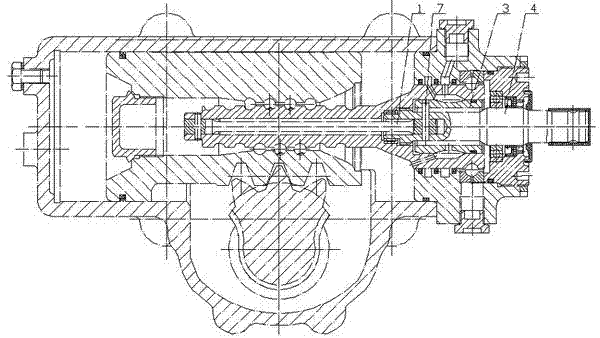
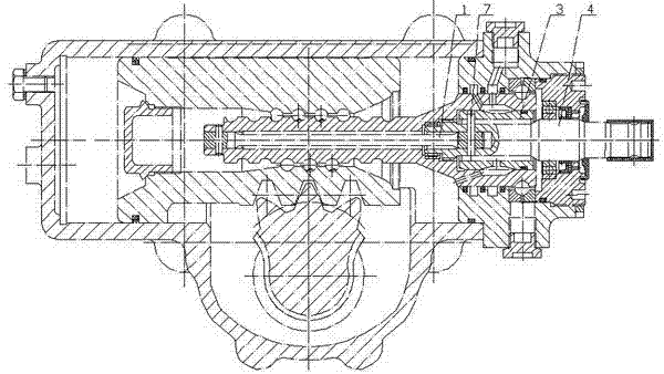
[0009] Figure 3 shows the new structure of the anti-leakage oil seal at the shaft end of the automobile hydraulic power steering gear. The positioning pin 6 for fixing the torsion bar 1 and the input shaft is designed inside the power steering gear, and a positioning pin 7 fixes the valve sleeve 3 and the torque The relative positions of the three parts of rod 1 and input shaft 4 reduce the difficulty brought by multiple positioning between workpieces, reduce the difficulty factor of the process, and cancel the figure 1 The input shaft and the positioning pin 2 of the valve sleeve, the positioning pin 6 and the O-ring 5 of the torsion bar and the input shaft of the original automobile hydraulic power steering gear shaft end anti-leakage sealing structure are truly "one-star pipe" The function of "three" fundamentally solves the phenomenon of slow leakage of high-pressure oil in power steering gears.


PUM


Abstract

The invention discloses a novel oil leakage preventing sealing structure for an automobile hydraulic power steering gear shaft end and relates to the technical field of automobile power steering gears. The novel oil leakage preventing sealing structure is characterized in that a positioning pin of a fixed torsion bar and an input shaft is designed inside a steering gear; the relative positions of a valve bush, a torsion bar and the input shaft are fixed by one positioning pin, so that the difficulty in processing caused by multiple positioning parts among workpieces is reduced, the difficulty coefficient of the process is reduced, a positioning pin of the input shaft and the valve bush, the positioning pin of the torsion bar and the input shaft and an O-shaped sealing ring in the oil leakage preventing sealing structure before improvement are eliminated and three functions by one device are really achieved. In addition, the phenomenon that high-pressure oil of the power steering gear often slowly leaks is fundamentally solved. Compared with the prior art, the novel oil leakage preventing sealing structure has the advantages that the phenomenon that the outer end of the input shaft leaks oil is avoided and the quality of the automobile hydraulic power steering gear is improved; and in addition, the cost is reduced, and thus the novel oil leakage preventing sealing structure is worthy of being popularized and applied.

Description

technical field [0001] The invention relates to the technical field of automobile power steering gears, in particular to a new oil leakage-proof seal structure at the shaft ends of automobile hydraulic power steering gears. Background technique [0002] Automotive hydraulic power steering is far more difficult than mechanical steering in terms of production and processing technology, equipment and inspection tools. In rotary valve power steering, the processing, manufacturing, assembly and adjustment of the rotary valve is the whole process. The core technology of power steering gear. The rotary valve power steering gear is a typical hydraulic servo system, and all the work is carried out under dynamic conditions, which requires that the servo parts (including input shaft, torsion bar, valve sleeve, steering screw) not only Meet the dimensional accuracy of the parts, and ensure the positional accuracy after assembly. The shaft end oil leakage prevention structure of the po...

Claims


Application Information

Patent Timeline
Patent Type & Authority Applications(China)
IPC IPC(8): F16J15/16B62D5/06
Inventor 刘建华
Owner DALIAN RUIGU SCI & TECH
Why Eureka
Eureka Blog
Learn More