Heavy-calibre ball valve

A large-diameter, ball valve technology, applied in valve details, valve device, valve shell structure, etc., can solve problems such as valve seal failure, easy erosion damage, and inability to work normally.

Inactive Publication Date: 2012-09-19
BAOYI GROUP
View PDF6 Cites 14 Cited by
  • Summary
  • Abstract
  • Description
  • Claims
  • Application Information

AI Technical Summary

Problems solved by technology

[0003] The ball valve with the existing structure has the following problems under actual working conditions: 1) Since the valve body and the end cover, and the end cover and the pipeline are connected by flange gaskets, the seal between the valve seat and the valve body, the valve stem and the pipe The seal between the bonnets adopts O-shaped rubber sealing rings; once a fire occurs in the gas pipeline system, the product structure does not have the fire protection function, and the flange gasket and O-shaped rubber sealing rings will be burned, and the fire will spread to the outside of the valve and The entire pipeline downstream of the pipeline has brought serious safety problems to the gas equipment system and people's lives and property; 2) This product is often used in urban underground pipelines, and the seal between the valve body and the end cover, and between the two ends of the end cover and the pipeline is uniform. The flange-gasket type is adopted. When the gas medium leaks due to the failure of the gasket, it is difficult to find and deal with it in time, leaving serious safety hazards; 3) The sealing ring on the valve seat is usually made of organic synthetic plastic, which is composed of a sphere. Soft-hard seal pair, its disadvantage is that the high-speed fluid is easy to wash and damage the plastic sealing ring on the valve seat during the valve switch process, so that the valve seal will fail and cannot work normally

Method used


Image

  • Heavy-calibre ball valve
  • Heavy-calibre ball valve
  • Heavy-calibre ball valve

Examples


Embodiment Construction

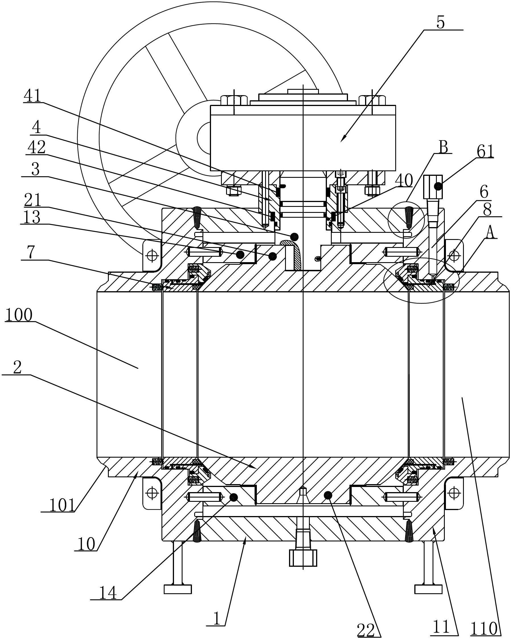
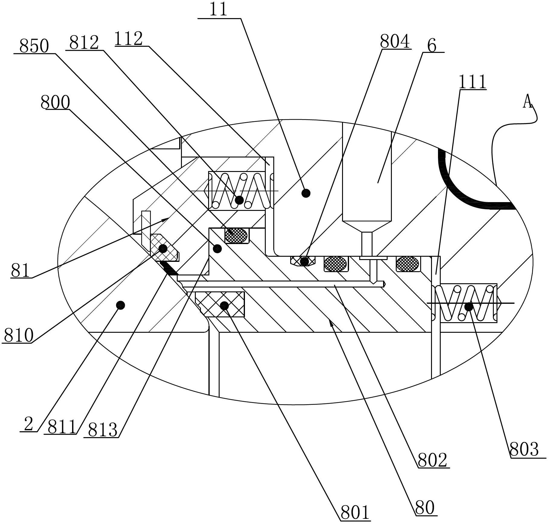
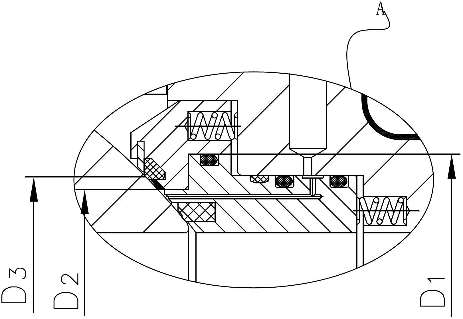
[0029] Such as Figure 1-3 As shown, a large-diameter ball valve disclosed in the present invention includes a valve body, and the valve body includes a main valve body 1 provided with a valve cavity, a left valve body 10 provided with an inflow channel 100 and a valve body provided with an outflow channel 110 The right valve body 11; the left and right valve bodies 10, 11 are welded on both axial sides of the main valve body 1 to form a welded combined valve body, forming a valve cavity connected to the inflow channel 100 and the outflow channel 101; the main valve body 1 and the left and right The welding of the valve body 10, 11 is a narrow gap double V-shaped groove weld 9 welding (such as image 3 shown), can greatly reduce the welding groove cross-sectional area and weld metal filling amount and improve efficiency; the left and right valve bodies 10, 11 are provided with The welding groove 101 for valve welding on the pipeline (the welding groove 101 in this specific em...


PUM


Abstract

The invention relates to a ball valve, in particular to a heavy-calibre ball valve. The heavy-calibre ball valve comprises a valve body, valve base assemblies, a ball body, a valve rod and a drive device, wherein a fireproof sealing device is arranged between the valve rod and the valve body; the valve body comprises a main valve body which is provided with a valve cavity and left and right valve bodies which are arranged on two sides of the main valve body; the left and right valve bodies are welded on two sides of the main valve body; the left and right valve bodies are provided with welding beveled edges which enable the valve to be welded on a pipeline relative to the end part of the other end welded with one end of the main valve body; a flow-in channel and a flow-out channel communicated with the valve cavity are formed in in the left and right valve bodies; a left valve base assembly matched with the ball body is arranged on one side inside the flow-in channel toward the valve cavity; and a right valve base assembly matched with the ball body is arranged on one side inside the flow-out channel toward the valve cavity. The welded type combined valve body is adopted and welded on the pipeline, so that a working medium is effectively prevented from leaking and fire is prevented from spreading during the fire disaster; and meanwhile, the weight of the valve can be lightened and the maintenance fee of a flange disc can be saved without using a flange disc.

Description

technical field [0001] The invention relates to a ball valve, in particular to a large-diameter ball valve. Background technique [0002] The main structure of the ball valve used on the existing large-diameter pipeline for intercity gas transmission is: including a valve body, a valve cover, a ball, a valve seat, a valve stem and a driving device, and the rotation of the valve stem drives the rotation of the ball to control the valve. The opening and closing state; the valve body is provided with an inflow channel for the flow of working medium, an outflow channel, and a valve cavity connecting the inflow channel and the outflow channel. The ball is a round ball with a diversion hole. The middle cavity of the body is provided with a valve seat that cooperates with the ball. The valve seat is a soft sealing surface embedded in synthetic plastic material. The valve seat can move relative to the valve body. The soft-hard seal paired with high-quality materials and metal hard ...

Claims


Application Information

Patent Timeline
Patent Type & Authority Applications(China)
IPC IPC(8): F16K27/06F16K5/06F16K5/20F16K27/10
Inventor 张晓忠陈佑军张晓秋杨兆倩
Owner BAOYI GROUP
Why Eureka
Try Eureka