
Liquid reservoir

A liquid reservoir and container technology, which is applied in the field of liquid reservoirs, can solve problems such as vibration or high-pressure refrigerant impact, and achieve the effects of saving processing time, ensuring refrigerant suction, and avoiding resonance

Active Publication Date: 2014-10-22
ZHEJIANG SANHUA AUTOMOTIVE COMPONENTS CO LTD
View PDF7 Cites 0 Cited by
  • Summary
  • Abstract
  • Description
  • Claims
  • Application Information

AI Technical Summary

Problems solved by technology

[0007] However, there is a shortcoming in the existing liquid reservoir, that is, when it is affected by loads such as automobile vibration or the high-pressure refrigerant on the high-pressure side of the automobile air-conditioning heating and cooling system has a sharp pressure change and causes an impact, it does not consider absorbing its vibration or Impact of high pressure refrigerant

Method used


Image

  • Liquid reservoir
  • Liquid reservoir
  • Liquid reservoir

Examples


Embodiment Construction

[0026] In order to have a clearer understanding of the technical features, purposes and effects of the present invention, the specific implementation manners of the present invention will now be described with reference to the accompanying drawings.

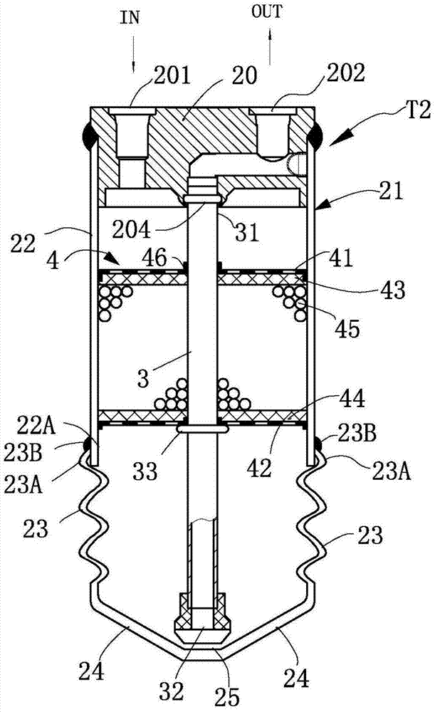
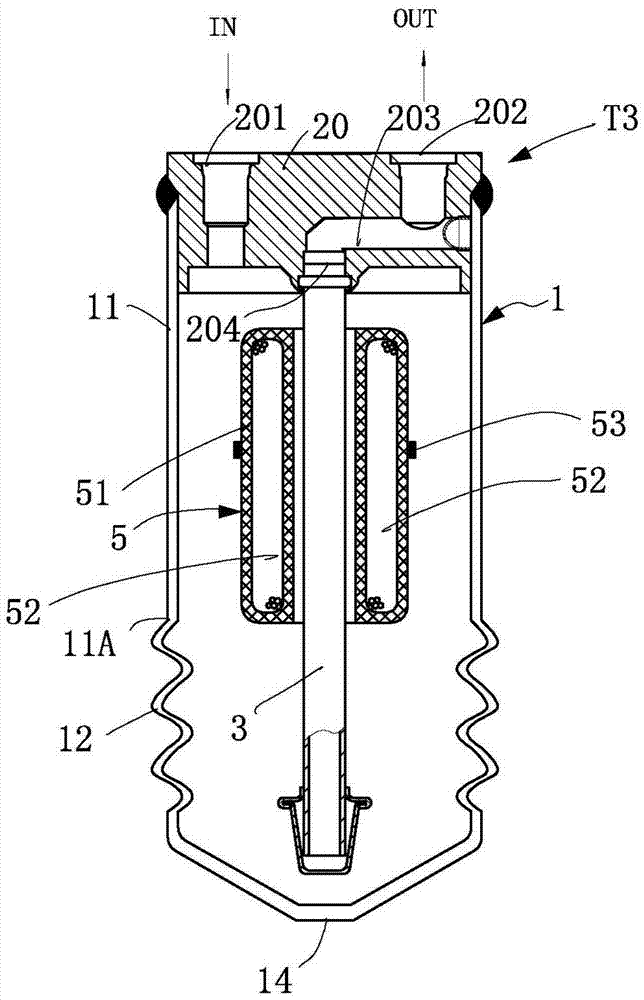
[0027] Refer to the following Figure 1 to Figure 4 Embodiments of the present invention will be described in detail.

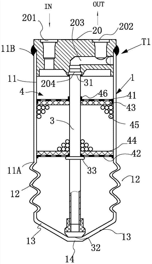
[0028] figure 1 It is a cross-sectional side view of an embodiment of the liquid reservoir T1 of the present invention. The basic structure of this reservoir T1 is the same as that shown in FIG. 5 of the aforementioned Patent Document 1, except that it does not have the supporting member 7 in FIG. 5 .

[0029] figure 1 Among them, the container 1 composed of cylindrical parts mainly includes a cylindrical portion 11 constituting the upper half of the container 1 and a corrugated portion forming the side wall of the lower half of the container 1, the corrugated portion 12 of the lower half The corrugated part...


PUM


Abstract

The invention relates to a liquid reservoir, which comprises a container, an end plate, an extraction tube and a drying part, wherein the container consists of bottom cylindrical parts; the end plate is provided with a refrigerant inlet and a refrigerant outlet; the extraction tube is kept pendent from the end plate used for blocking the upper ends of the cylindrical parts and is arranged at a slightly central position of the container; the drying part is arranged outside the extraction tube; the upper end of the extraction tube is connected with the refrigerant outlet; a liquid refrigerant retained at the bottom of the lower end of the container from the lower end of the extraction tube flows out through the refrigerant outlet; and the container consisting of the cylindrical parts comprises a corrugated part which is formed on the lower part of the container. By the liquid reservoir, the bottom of the lower end of the container is formed by the corrugated part, so automobile vibration and other load influences or impact influence brought by change of high-pressure refrigerant pressure can be absorbed through the corrugated part, and stable operation of the liquid reservoir can be maintained; and moreover, resonance of a high-pressure pipeline and squeal of an expansion valve can be avoided.

Description

technical field [0001] The invention relates to a liquid receiver, in particular to a liquid receiver for a cooling and heating system of an automobile air conditioner. Background technique [0002] Such a liquid reservoir is shown in FIG. 5 of Japanese Patent Document 1 (Composition Laid-Open Hei 6-27232), the bottom of which is provided with a supporting member supporting the lower part of the suction pipe, and the supporting member is held around the bottom of the liquid reservoir, and, In order to prevent the pipette from falling down, a prescribed gap d' is maintained between the bottom of its support member and the bottom of the liquid reservoir. In addition, a disc-shaped upper plate and a disc-shaped lower plate are provided in the middle of the liquid suction tube, and a desiccant is filled between the upper and lower discs through the felt F. In addition, a plurality of through holes serving as air holes are formed on the upper and lower discs. [0003] In additi...

Claims


Application Information

Patent Timeline
Patent Type & Authority Patents(China)
IPC IPC(8): F25B43/00
Inventor 祝颖安
Owner ZHEJIANG SANHUA AUTOMOTIVE COMPONENTS CO LTD
Learn More