
Enhanced condensation heat transfer tube

A technology of heat transfer tubes and regular changes, applied in the field of heat transfer tubes, can solve the problems of low heat transfer performance of condensers, achieve the effects of weakening the tube bundle effect, enhancing heat transfer performance, and accelerating dripping

Active Publication Date: 2014-12-31
GOLDEN DRAGON PRECISE COPPER TUBE GROUP
View PDF10 Cites 0 Cited by
  • Summary
  • Abstract
  • Description
  • Claims
  • Application Information

AI Technical Summary

Problems solved by technology

[0004] The technical problem to be solved by the present invention is to provide an enhanced condensation heat transfer tube, which improves the heat transfer performance of the heat transfer tube used in the condenser through the enhanced heat transfer technology, and solves the problem of low heat transfer performance of the existing condenser

Method used


Image

  • Enhanced condensation heat transfer tube
  • Enhanced condensation heat transfer tube
  • Enhanced condensation heat transfer tube

Examples

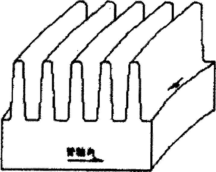
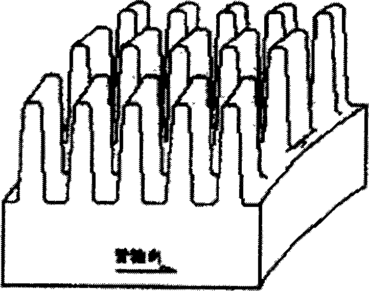
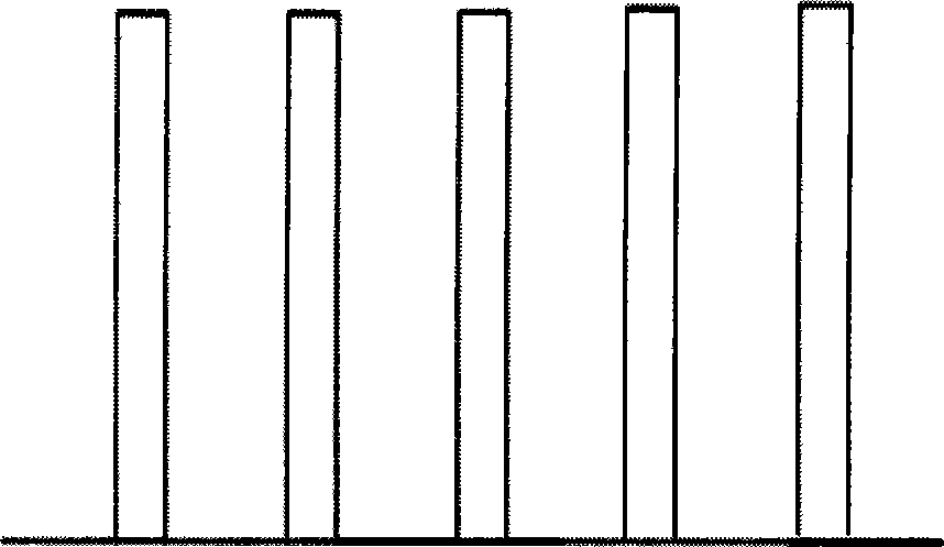

Embodiment Construction

[0024] In order to make the above objects, features and advantages of the present invention more comprehensible, the present invention will be further described in detail below in conjunction with the accompanying drawings and specific embodiments.

[0025] refer to Figure 4 , shows the front projection view of the first embodiment of the enhanced condensation heat transfer tube of the present invention. In this preferred embodiment, the outer surface of the heat transfer tube has spiral fins, and the distance between the fins is one along the axial direction. The changing law of width and narrowness; among them, the helical fins are provided with 26-60 fins per inch along the axial direction, the spacing between the axial fins is 0.4-1mm, the thickness of the fins is 0.1-0.4mm, and the helix angle range of the helical fins It is 0.3~1.5°, and the fin height ranges from 0.4~1.5mm; in addition, the spiral fin can be smooth, or it can be a slotted fin that is grooved on the top...


PUM


Abstract

Disclosed is a heat transfer pipe for enhanced condensation. The outer surface of the heat transfer pipe is provided with helical fins. The fins, spaced apart axially, vary in width in a regular pattern. The heat transfer pipe can change the surface tension of a condensation liquid film between the fins on the outside of the pipe, increasing the heat exchange effects by condensation outside the pipe.

Description

technical field [0001] The invention relates to the technical field of heat transfer tubes, in particular to an enhanced condensation heat transfer tube. Background technique [0002] With the advocacy of energy-saving and high-efficiency concepts, the design of condensers requires gradual improvement of heat transfer performance, and high-efficiency heat transfer tubes are the core factors affecting the heat transfer performance of condensers. Publication No. CN1982829A discloses a copper heat exchange tube with smooth fins with a triangular cross-section outside the tube. This smooth fin can increase the heat transfer area and reduce the condensate film when used in a condenser. Accelerate the speed of condensate dripping, and the heat exchange efficiency is higher than that of the light pipe. However, the condensate between the smooth fins is easy to "bridge", so that the flow of the condensate is not smooth, and the condensation thermal resistance on the fins increases...

Claims


Application Information

Patent Timeline
Patent Type & Authority Patents(China)
IPC IPC(8): F28F1/36F28F13/00F25B39/04
CPCF28F1/36F28F13/182
Inventor 武永强王志军孙新春王晨辉张小广李前方
Owner GOLDEN DRAGON PRECISE COPPER TUBE GROUP
Learn More