High precision leveling method and high precision leveling device for large optical element

An optical component, high-precision technology, applied in the direction of optical testing flaws/defects, etc.

Active Publication Date: 2012-09-19
ZHEJIANG UNIV
View PDF3 Cites 18 Cited by
  • Summary
  • Abstract
  • Description
  • Claims
  • Application Information

AI Technical Summary

Problems solved by technology

[0004] The purpose of the present invention is to p

Method used


Image

  • High precision leveling method and high precision leveling device for large optical element
  • High precision leveling method and high precision leveling device for large optical element
  • High precision leveling method and high precision leveling device for large optical element

Examples


Embodiment

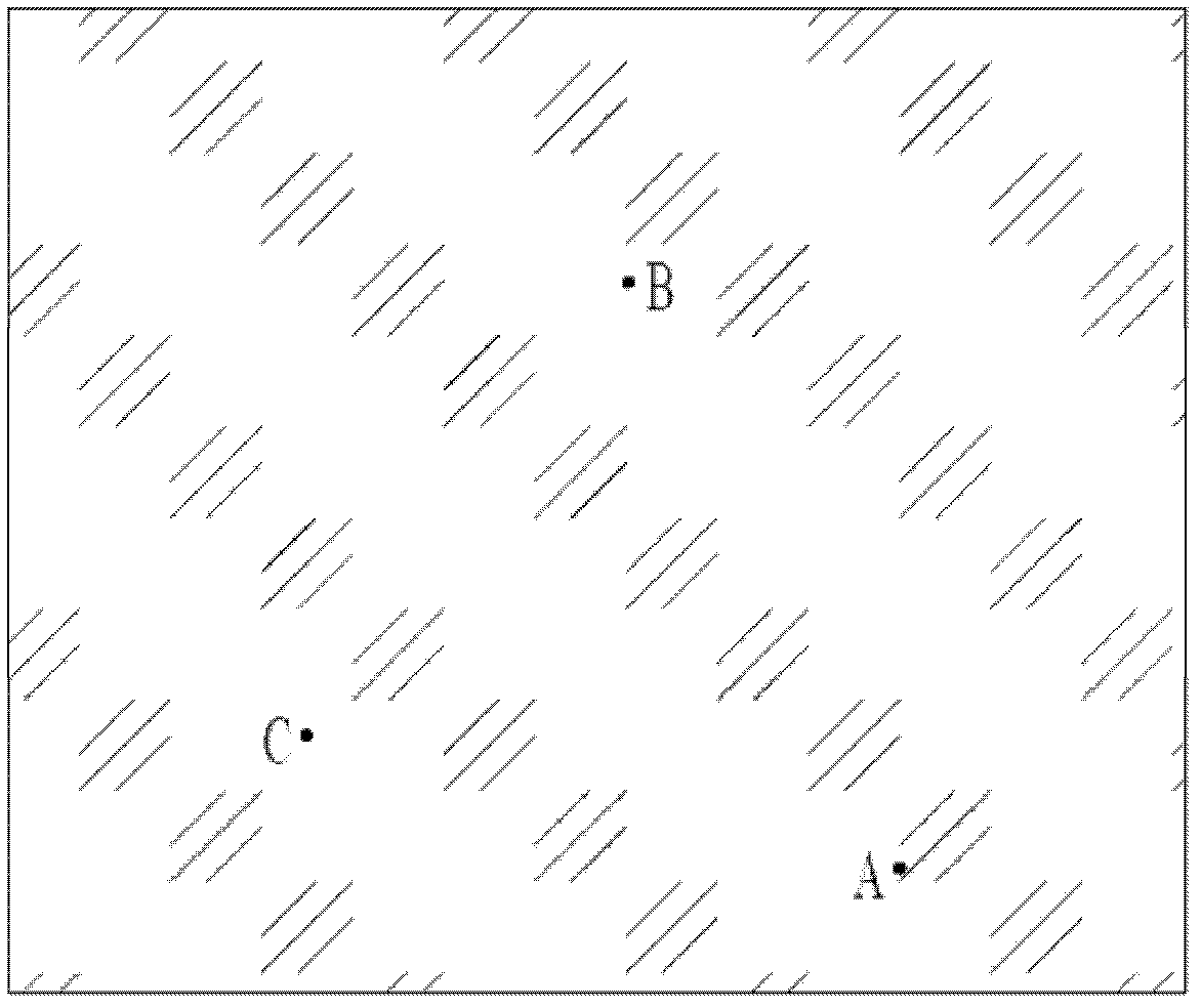
[0055] Leveling detection is performed for high-precision leveling of large-sized optical components. In the inspection, the surface size of the optical element is selected to be 430mm×430mm, the magnification of the high-power microscope is 16 times, and the grayscale image is collected in the axial direction of the microscope with a step length of 0.06mm. Figure 7 Shown is part of the dark field grayscale image of the feature points collected on the surface of the component, and the grayscale information entropy value of the image is calculated to obtain the results shown in Table 1

[0056] Table 1. Figure 7 The gray information entropy value of each dark field gray image in

[0057] image serial number

1

2

3

4

Gray information entropy value

2.4272

2.3543

2.3733

2.4326

[0058] From Table 1, it can be seen that the gray information entropy value of frame (b) is the smallest. Compared with the four im...


PUM


Abstract

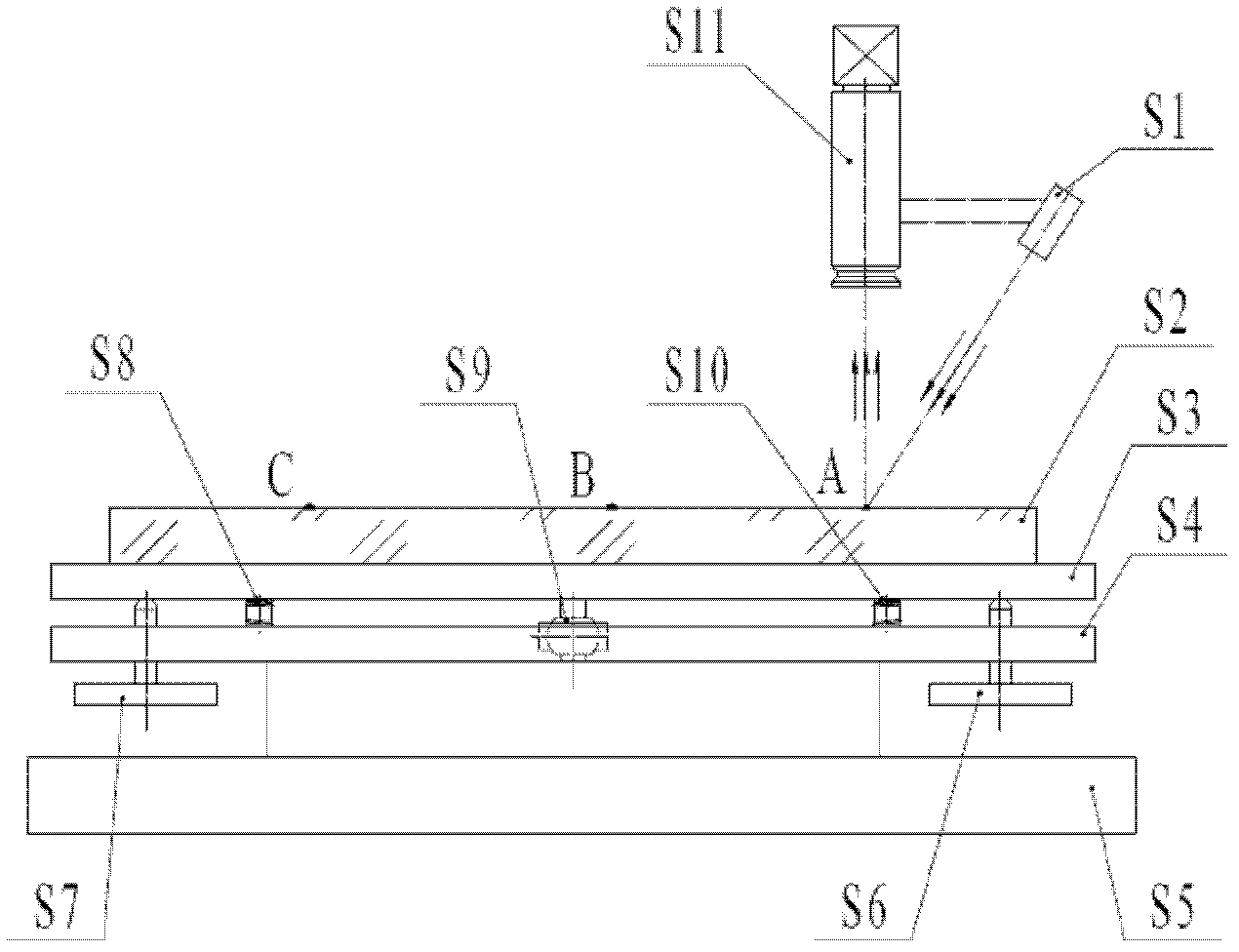
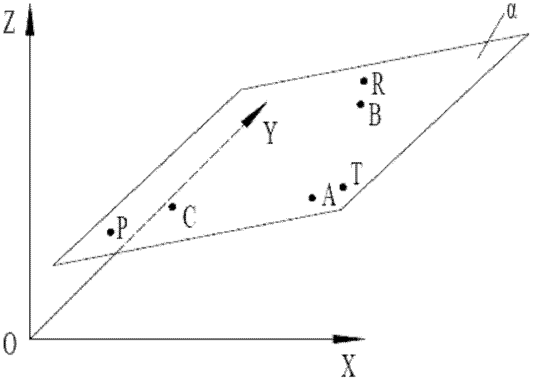
The invention discloses a high precision leveling method and a high precision leveling device for a large optical element. The method includes: using a high-power microscope to perform continuous multiple dark field grey level image acquisition to three characteristic points at different positions on the surface of the optical element, calculating image grey level information entropy, fitting thegrey level information entropy with an axial moving distance curve of the microscope, searching for a minimal value in the curve to obtain a focusing position, and obtaining defocusing amount of eachcharacteristic point. The leveling device is in a two-plate and elastic pre-tightened design. Pitching and lateral swaying of the leveling device are adjusted through two points. By building a conversion model of the defocusing amount and adjusting amount to convert the defocusing amount of the three characteristic points into the adjusting amount of the two adjusting point, leveling operations can be performed. The problem of defocusing of the large optical element due to non-parallelism of the optical element and a focal plane of the microscope during a full-range scanning and detecting process using the microscope is solved.

Description

technical field [0001] The invention relates to a high-precision leveling method and device for large-scale optical components. Background technique [0002] In the full-range scanning dark field defect imaging detection of the surface of optical components, some components to be tested are large in size and some have wedge angles. For example, the size of the sampling mirror used in the ICF (inertial confinement fusion) system reaches 415mm× 415mm, with a wedge angle of 0.4°. After conversion, the deviation of the lens in the thickness direction reaches 2.9mm, while the focal depth of the microscope is only tens of microns at high magnification. In the process of imaging, a clear image cannot be collected due to defocus, which will affect the recognition of defects, and will cause the corresponding defect images to not be collected during the digital interpretation of high-magnification defects, causing misreading and misreading. It is necessary to find a fast and high-pre...

Claims


Application Information

Patent Timeline
IPC IPC(8): G01N21/88
Inventor 杨甬英曹频陈晓钰王世通卓永模
Owner ZHEJIANG UNIV
Why Eureka
Try Eureka